
This article discusses repair and calibration of the Hickok 6000 tube tester. Models 6000A and 6005 are the same with only minor feature differences that are not relevant to tube test calibration, therefore the discussion is applicable to those models as well. Serious electrical voltages are present, repairs should only be attempted by a qualified technician. Copyrighted by Bob Putnak, all rights reserved.
Introduction
Hickok 6000 series is a compact mutual conductance tube tester.
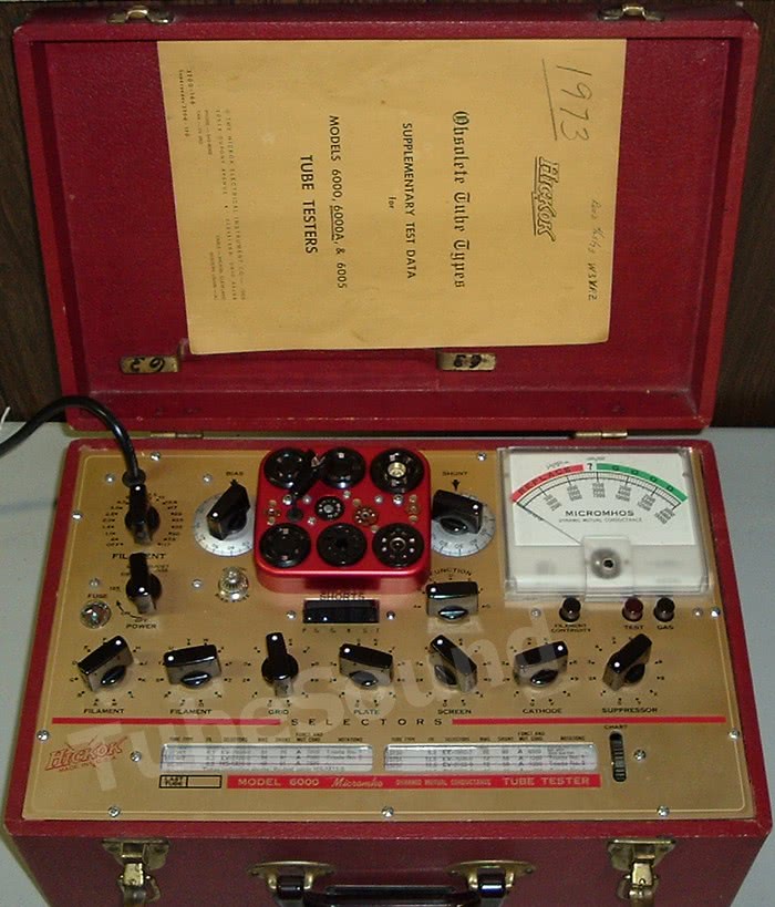
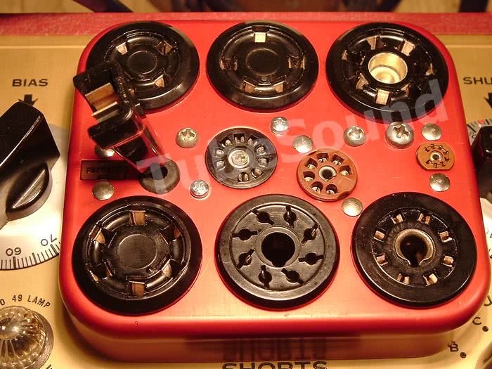
Most Hickok tube testers fall in two categories: those that use a 5 vac signal voltage and those that use a 2.5 vac signal voltage. Otherwise, most Hickok’s are remarkably alike (except for the really expensive models such as 539C or 752…). The 6000 series in the 2.5 vac signal voltage group. The compact size of the 6000 is a welcome asset to any technician’s workbench because space is always at a premium. The 6000 series also has a replaceable socket panel. One panel has an older compliment of sockets (4-pin through 9-pin-miniature sockets); the other panel has a newer socket compliment (compactron & novar sockets instead of the antique sockets). This system allowed easy replacement of worn out sockets — the customer simply purchased a new panel from Hickok. The setup chart configuration for the Shunt control gives “Good-Bad” readings, which were previously called the “English” readings in older Hickok testers. In fact, the Shunt control was named “English” on older models. The chart also provides a micromhos score for tubes that have transconductance (ie – not rectifiers, not diodes, not thyratrons…), and the Shunt control must be repositioned to the red dot on the Shunt control that is appropriate for that micromhos reading. For example, if the chart says “2000” and you had some reason to benefit from knowing the micromhos score (which is seldom the situation), you would ignore the chart’s shunt number and instead set the shunt control to the red dot near “73” which is the 3000 micromhos range. For most testing needs of a technician, the good/bad scale is convenient and appropriate.

Need paperwork for your Hickok 6000? remastered paperwork package for Hickok 6000 — manual, schematic, remastered factory calibration document, and obsolete tube chart data supplement. $9.99 free ship USA.
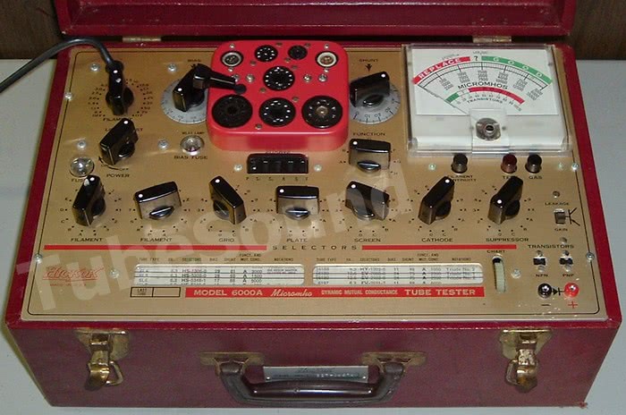
Vintage is approx 1957. The 6000 sold for $182 in 1958. Dimensions: 17 x 12 x 8 (inches) and weight 16-lbs. Model 6005 is the same tube tester but integrates multimeter functions. Model 6000A has basic transistor testing capability, which I doubt that anyone uses today. The 6000A has the newer socket panel with compactron and novar sockets, but without the antique sockets (4-pin, 5-pin, etc.)

The socket panels are not interchangeable between 6000 and 6000A due to a different connection plug on the underside. As a sidenote, this socket panel makes it very difficult to install socket-savers if you still want to close the case lid. It can be done, but it requires a lot of work and creative thinking. See my article [HERE].
Repair and Calibration
A thorough explanation of the Hickok test method, calibration voltages, and the equipment that was used to make those voltage measurements is in a United States military document TM 11-6625-274-35 for military TV-7 series of tube testers. This information is applicable to most Hickok tube testers (not all), with the caveat that some models use 2.5 vac signal voltage instead of 5.0 vac. It explains the voltages for the plate, screen, grid, signal and the method used to obtain those measurements. A factory calibration document for the 6000 series also exists (and has one typo mistake) and closely follows the voltages in the military TM document. Remove the roll chart and do not reinstall into your repairs are finished. The fundamentals for starting the calibration: all knobs and the meter itself are indexed at zero, check all resistors and potentiometers for accuracy and replace where necessary. Install new fresh capacitors, especially the small electrolytic across the meter. When working on any Hickok, or when working on any piece of equipment with a sensitive panel meter (such as a vtvm), it is a good idea to clip a jumper wire across the panel meter when you are making any resistance readings inside the equipment. Otherwise, you could accidentally apply voltage from your ohmmeter across the panel meter, and a sensitive meter can be easily and quickly destroyed. Of course, be sure to remove the jumper before reapplying power to the equipment.
Clean all socket pins.
Clean all switches with Deoxit. It is very important to always treat Hickok pots internally with Deoxit or other quality electrical lubricant because these pots tend to have erratic continuity otherwise. If you do nothing else, you will have done something important towards accuracy and repeatability. Inspect all wiring (AC power cord, and also each wire connection at every tube socket pin). A grounded line cord is a smart and much safer replacement since the tester has a metal faceplate. Remove both bulbs (#81 fuse bulb and neon shorts lamp), clean bulb connections and sockets, reinstall. Make sure that the bulb types are correct and not substitutes. If you need bulb replacements, use only vintage USA-manufactured stock. Remove and check both internal tubes (#83 and 5Y3) with another quality tube tester. Check for balanced plate sections. The 6000 does not lend itself to using a solid-state #83 replacement, there is not enough line adjustment on the rheostat to account for the load that the #83 tube places on the transformer. Even with circuit modifications, I would not trust the accuracy of any 6000 with a solid-state 83.
Shorts Test
The Hickok 6000 shorts test is automatic. A series of five neon lamps is used to indicate shorts between elements. The lamp(s) will turn off when the machine detects a short. The owner’s manual has a chart to explain the relationship between which neon lamp(s) go dark in relation to which tube elements are shorted. The Hickok calibration instructions provide an easy way to check for basic shorts functionality. “With Cathode and Suppressor switches in the same position (Example: 1-1, 3-3, etc) through the range of positions, and with the exception of position 0-0, the short indicator lamps should show a cathode to suppressor short.”
Panel Meter
The Hickok 6000 meter is 100µA, resistance 1165 ohms, thereby ohm’s law reveals that it takes 116.5mV to achieve full scale.
This meter has a variable resistor mounted on the outside and is part of these specs. If you suspect problems with the meter, connect an accurate millivolt DMM across the red and black meter terminals and you should get 58.25 mV at half scale “LINE”. A measurement of 58.2 or 58.3 would be fine.

Calibration configuration uses the 6L6 tube setup: H-S-5-3-4-8-1. Leave the bias and shunt controls at zero unless otherwise indicated. Function switch at ‘A’.
Line calibration, Signal Voltage, Plate Voltage, High Screen Voltage
The 6000 meter automatically reads the “Line test” when you turn it on. That is why the pointer goes to mid scale when you power on the machine. The purpose of the Line Test is to allow the operator to know when the machine is set at the correct operating voltages to make an accurate tube test. The Line is set accurately on a 6000 when a Signal Voltage of 2.5 vac is present when the panel meter reads LINE (half-scale).

The signal voltage is the most important factor for mutual conductance tests. The signal voltage can be measured using a DMM, no shunts required. Connect your meter to pins 5 and 8 using an octal test socket, press TEST, and turn the LINE ADJUST control until you measure 2.50 vac. Release the test button and the panel meter pointer should read LINE. If not , adjustment is made using the internal pot with the blue plastic knob. Repeat test several times to ensure accuracy.
The plate voltage is automatically set by the Line. The plate voltage is measured with a 1000 ohms per volt meter on the 250V scale at pins 3 and 8 when the TEST button is depressed. A modern DMM can be shunted with a 250k resistor to simulate the original meter used to make this measurement. 150V ±3V.

The voltage is completely dependent upon the transformer, the #83 rectifier tube, and the accuracy with which you set the Line above. If you find that your plate voltage is outside of the 150-155 vdc range (measured 1000 Ω/v) when setting the signal voltage to 2.50 vac as indicated above, which may be the situation if the transformer windings are not perfect in your particular machine, then calibrate the line using the plate voltage within 150-153v range (measured 1000 Ω/v) that will bring your signal voltage as close to 2.50 vac as you can get. it Sometimes compromises are necessary.
The high screen voltage is measured between pins 4 and 8 when the TEST button is depressed. A modern DMM can be shunted with a 250k resistor to simulate the original meter used to make this measurement. 135V ±3V. This is one small difference from the military specs, where the screen voltage was referenced at 130V. The Hickok 6000 factory calibration document notes 135v on this model. The voltage is completely dependent upon the transformer, the 5Y3 rectifier tube, and the accuracy with which you set the Line above.

Plate supply and Screen supply balance
Your tester will have a little better accuracy with closely balanced #83 and 5Y3 rectifier tubes. Testing each of those tubes for balanced plate sections in another tube tester is very satisfactory. Be sure to check each plate section using a “Life Test”, which is best way to see if the rectifier is close to end-of-life. That said, plate balance is further verified with a scope. Configure your scope to its highest volts/div, Line trigger source, and use a 10X probe. Make sure tube tester is unpowered and unplugged before making and removing scope connections. I would point out that neither the military TM document nor the hickok factory calibration procedure mentions any need to check this balance, and certainly scopes were commonplace when those documents were created. In the old days, technicians were very practical and realized that “perfect balance” was neither necessary nor all that meaningful for the intended purpose of a tube tester (which is to evaluate a tube as probably good or probably bad, not to give it some almighty “score”). In the modern world people take things to extremes that are often beyond what the manufacturer intended. There is no doubt that ‘balanced’ will be slightly more accurate than ‘unbalanced’, but unless you have one very substandard plate section it is really not that big of a deal. The factory technicians that created the calibration procedure did not even feel that it was important enough to mention it. I would also point out that it is very common for one plate section of a used #83 tube to be very weak under load. This defect will show up on a tube tester, so be sure that you replace any #83 that tests defective. The plate supply is tested as follows: scope probe on octal test socket pin 3, common on pin 8, press TEST button and observe balanced peaks. If one peak is reasonably higher than another, then your #83 tube is not perfectly balanced. On the 6000, the screen supply is tested as follows: scope probe on transformer “K” winding tap, scope common on transformer “N” winding tap, press TEST button and observe balanced peaks. If one peak is reasonably higher than another, then your 5Y3 tube is not perfectly balanced. Explained in more technical terms, the screen supply balance is tested by connecting the scope ground to the transformer center tap for the 5Y3 plate windings, and the scope probe is connected to the transformer center tap of the 5Y3 filament.
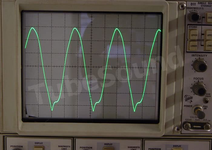
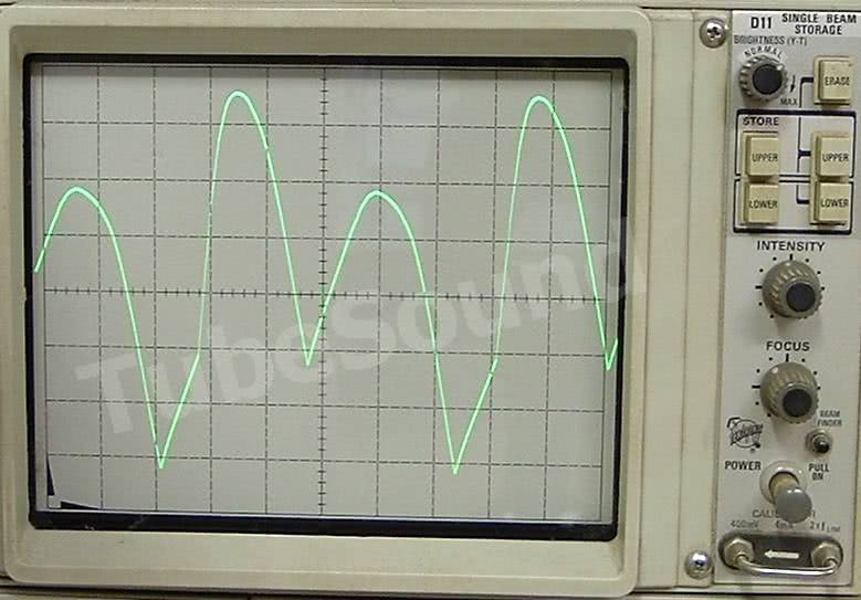
Of course, this test procedure is applicable to other Hickok’s as well. The pattern that you see will be similar for both, so there is no reason to show both. Here are examples of balanced and unbalanced supply. (The unbalanced supply photo is grossly unbalanced in this example — one plate section is a dud). Again, the pattern is easiest to see if you use “Line” trigger source on your scope, then each plate section will be displayed one-rounded-peak-after-another.
Grid Bias Voltage and Low Screen Voltage These two interact with each other and are therefore discussed together. Make the grid bias adjustment first before performing the low screen voltage adjustment. Then re-check each because there is interaction between them.
The grid bias voltage is measured between pins 5 and 8 with the bias control at 100 and the TEST button is depressed.
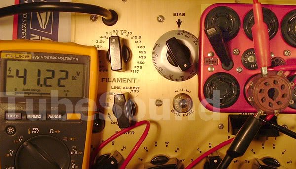
A modern DMM can be shunted with a 50k resistor to simulate the original meter used to make this measurement. (-40 vdc ±2V) . Grid bias adjustment: remove power and unplug tester from the mains before making any adjustment. Prop machine on its backside with rectifier tubes facing upward. Locate the standee resistor that has two sliding taps on it. The bottom slider, orange wire side, is the grid bias adjustment. Slide upward to increase voltage, slide downward to reduce voltage. Note that this standee resistor is rather fragile so make sure that sliding tap is completely loose before trying to slide it. When tightening the sliding tap, do not over-tighten. Repeat test and adjustment until you achieve as close to -40 as you can. The next three measurements are to verify close accuracy of your bias control. There is no separate adjustment for them beyond adjusting the entire grid bias that I just explained. Each of these measurements of the bias control setting is verified in military document TM 11-6625-274-35, page 39.
Turn the bias control to read 22. A modern DMM can be shunted with a 10k resistor to simulate the original meter used to make this measurement. (-3.0 vdc ±0.2V) . The Hickok 6000 factory calibration document that indicates (-3.3) is a typo.

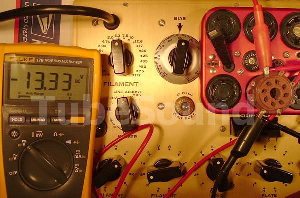
Turn the bias control to read 50. A modern DMM can be shunted with a 50k resistor to simulate the original meter used to make this measurement. (-13.4 vdc ±1V).
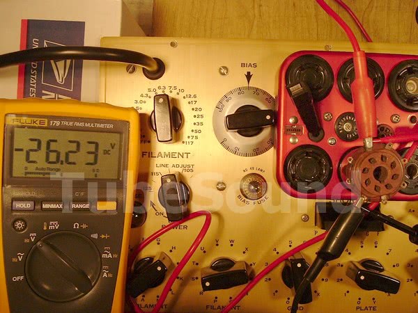
Turn the bias control to read 75. A modern DMM can be shunted with a 50k resistor to simulate the original meter used to make this measurement. (-25.8 vdc ±1V).
The low screen voltage is measured between pins 4 and 8, function switch at ‘B’, with the bias control at zero, and the TEST button is depressed. A modern DMM can be shunted with a 120k resistor to simulate the original meter used to make this measurement. (56 vdc ±2V) . Low screen voltage adjustment: remove power and unplug tester from the mains before making any adjustment. The upper sliding tap (gray wire) on that standee resistor makes this adjustment. Sliding the gray wire slider upward will reduce the low screen voltage. Repeat test and adjustment until you achieve as close to 56v as you can. Note: as mentioned above, these two adjustments interact with each other, so you need to re-check them again and repeat process if necessary.

Bridge Balance Test
Check meter bridge balance by connecting a large power resistor (10 watt+), 10K resistance, between pins 3 and 8, with shunt control at the 3000 micromhos red dot position. Press TEST and verify that meter needle remains at zero or within a division or so, which is optimal. Slowly rotate the shunt each direction while pressing TEST, and see that meter pointer remains reasonably balanced. If your balance is consistently bad everywhere, then you have a legitimate issue to correct, and your only solution is to remove the shunt pot (which is a dual section pot) and balance both sections. This requires unsoldering the two halves and tedious work. In evaluating the balance, common sense is required. The shunt pots are old-fashioned, analog, mechanical pots. They were not precision manufactured. You will not find them perfectly balanced across the entire range of the shunt control and that is normal. Do not “find” a problem where none exists. These are old analog test instruments that were never manufactured for or intended for laboratory precision. Use common-sense.
MUTUAL CONDUCTANCE TEST
I will explain what this test entails, but first I will suggest that there is no practical benefit to performing it because Hickok did not calibrate the tester at the factory with this method, and you should NOT make ANY adjustments based upon the result of this test. [NOTE: Dangerous test, could cause serious damage and is also a shock hazard if done incorrectly. See page 41 of TM 11-6625-274-35 for military TV-7 series of tube testers for a general understanding of the test if you are curious. Do NOT implement the test exactly the same way because the pinout and Gm test score will NOT be the same in a 6000 due to different signal voltage.] This test is a crude and misleading way to “simulate” a tube. Mathematically it is correct but does not in any way simulate how a real tube operates (the grid is not even part of this test). Hickok did not calibrate the red dots on your Shunt control using this test, nor does the factory calibration document make any mention of this test. The factory used a calibration tube — a real tube — a 6L6 of known value — and marked the Shunt dial according to the micromhos reading of that tube. (Using a calibration tube to mark the micromhos ranges is Step 9 of the Hickok 6000 factory calibration instructions. The calibration tube was the LAST step of the calibration procedure.) Therefore, the factory red-dots WILL be the accurate marks because they were marked using a calibration tube at the factory, so any changes you would make to re-mark the red dots will only create inaccuracy. In summary, the “simulation” test is to set the Shunt control at the red dot for the 3000 micromhos position. Connect an Isolated fixed current source of 5ma between pins 3 & 8. This requires either an ISO-Variac or combination Isolation transformer + Variac. (5ma can be calculated from a 50v source and 10k resistance.) When pressing Test, if meter needle deflects downward, swap connections at 3 & 8. The score (in theory) is 2000 micromhos on the meter, but many testers will read a little lower or higher, and that is perfectly normal. Again, my suggestion is that there is no real benefit to making this test unless you are having accuracy problems and have exhausted all other potential sources of the problem (rectifier tubes, plate/screen/grid/signal voltages, issues with the panel meter itself, dirty controls, incorrect or defective bulbs, etc.)
GAS TEST
With a known gas-free 6L6 tube, performing the gas test should not move the meter from zero. Shunt a 1-meg resistor between pins 5 and 7. The Gas Test should now move the meter approx one division.
Summary and Conclusion
To emphasize a few things that really make a difference: (1) continuity is critical — clean socket pins, clean bias and shunt controls, clean switches. People get caught up in adjusting voltages but often ignore the basics. Poor continuity in the control pots, switches, and socket pins will cause all kinds of test inaccuracy and inconsistency. (2) Make sure the rectifier tubes are good and reasonably balanced. (3) Check all voltages and be make sure your Line test is accurate vis-à-vis the 2.5 vac signal voltage. Those suggestions go a long way towards a reliable tester.

PROS:
- Compact size requires less bench area
- same basic Hickok mutual conductance test that has a good deal of inherent quality
- Shorts Test is easy to use because it is automatic
Limitations:
There is a reason why the 6000 series was one of the cheapest Hickok’s made. Regardless, it is still a good machine, but one needs to recognize its limitations.
- the entire machine is a design of compromises, which is why it was entry-level.
- the Dual-pot “Shunt” control (known as “English” control on earlier Hickok’s) is only consumer-grade quality, and does not lend itself to “accurate” Gm scores. There are fixed-positions for Gm testing. The dual-pot knob has red dots that define the three Gm scales on the meter, instead of fixed-switch Gm ranges. This red-dot-scheme was a significant cost-compromise. Gm scores on a 6000 should be considered “in the ballpark” numbers, nothing more. Of course, the Gm scores cannot be compared to machines with different test parameters. For example, in no way can these Gm scores be compared to those derived on a Hickok 539-series machine.
- Due to the compromised Gm scores testing, the 6000 series is best used as a Good-Bad tester, which is in-fact the default way to read the meter based upon the setup chart settings. This method is perfectly fine to evaluate tubes as a technician. Accurate/repeatable Gm scores require fixed Gm positions, such as those found on the 539-series, 752 models, and 533 models. Again, those Gm scores (even for machines with fixed Gm positions) cannot be compared to models with different test parameters.
- the fixed signal voltage is not ideal for all tubes
- a single transformer supplies all voltages, and it has a lot of sag during Gm tests, which cannot be properly re-compensated for. For example, the heater voltage of a 6L6 during Gm tends will easily fall below 6.0vac (I’ve measured it as low as 5.7vac). That is substandard if you are looking for the “best” tube evaluation you can get. Even if you metered the heater voltage and re-compensated the Line, you would still not be correctly re-compensating the bias, so you need to live with this limitation. The machine was not meant to be lab-grade. It was sold as a good quality entry-level machine for technicians to find bad tubes. Don’t expect more from it.
- like all cheap Hickok’s, the bias is not metered, nor do you know the exact bias that Hickok had in mind because the bias is set with the 0-100 number system. Even if you know the exact bias, you have no way to re-set the bias once the Gm load test is engaged.
- None of the test voltages are filtered (plate voltage, screen voltage, or bias). They are all pulsating DC.
- does not lend itself to replacing the #83 tube as easily as most Hickok’s
- if keeping the 83 tube, the tube tends to go bad rather quickly (one plate section always goes weak, especially under load). As tube ages, accuracy suffers.
- Shorts and Leakage (Gas) tests are inferior when compared to other tube testers such as a Sencore Mighty Mite (as one example).
Certainly the Hickok Gm test is better than a plain emission test for testing most tubes, but ultimately both test methods have their place. (A quality emission test is very good at finding bad tubes, so a good emission test certainly has a seat at the table). I think most tube enthusiasts and technicians should own a Hickok, but I also think that you need a second tester that does a much better job testing for shorts and leakage.
If you are serious in deriving Gm scores, the 6000 series is a poor choice. For that purpose, go with one of the 539 models or a modern-manufactured digital tube tester.