
Early this year I found this vintage Colin B. Kennedy Corp radio. Model 62LS lowboy console with model 54A shortwave unit. I recently finished rebuilding this radio. It is available for purchase (local pickup preferred, but crating and shipping can be arranged but will be quite expensive). It would make a beautiful addition to any old home or turn-of-the-century mansion. This beautiful antique radio is more than a radio — it is a beautiful piece of furniture as well. Colin B. Kennedy Corp marketed themselves as the “The Royalty of Radio”, and the high quality craftsmanship is readily apparent.

This is actually the second Kennedy console radio in my collection.
I have a model 20 console also. The schematics for both the 62LS long wave chassis and the 54A short wave unit are found in the full Volume #1 of Rider’s Perpetual Troubleshooters manual.
I do not know the exact vintage of this radio. The Bunis radio guide says that the Colin B. Kennedy had declared bankruptcy by 1926, although Bunis does list several Kennedy console models dating up to 1932. The original price was $259.50, which in ~1930 was truly a radio that only the wealthy could afford! And in fact, this radio did come from the estate of a wealthy English woman.

My model 62LS is different than model 62 listed in the Bunis guide. Model 62LS came with the shortwave unit, model 62 did not not. The 62LS cabinet has doors similar to the Kennedy model 20 console or the early Sparton wood consoles. The grill design is also different, and the cabinet is taller to accommodate the 54A short wave unit, and of course has the openings for the short-wave chassis dial and controls.
Dimensions = 51 high x 28.5 wide x 15 deep. (Inches)
Model 62LS uses the same #62 long wave chassis as does the standard console model #62. The model 62 in the Bunis guide shows two speakers. Model 62LS only has one speaker, and the model 62 Rider schematic clearly shows and describes only one speaker. The tube configuration uses all early Globe-style designations, which are (1) #280 rectifier, (4) #235 for RF,IF,Detector, (3) #227 for Osc., Detector, AF, and (2) #247 push-pull audio output. The speaker is a 12-inch electrodynamic, field resistance 2,250 ohms. The model 54A short wave unit has two tubes, being (1) #224 and (1) #227. The output of the short wave unit is tuned just like any “station.” The Rider documentation is not clear as to what this output frequency is for Model 54-A, and to add to the confusion, the output frequency of Model 54 is different from “Model 54 Globe Trotter.” (And yes, model 54-A is a little different from either of those models). The bottom of the Model 54-A Rider documentation says to refer to model 53-SW for calibration scale, so possibly the frequency provided in the Model 53-SW documentation is correct? According to Rider, the output of Model 53-SW was set at the factory at 1,000 kilocycles, and this frequency is adjustable. The short wave unit requires AC power, and also a wire supplying “B” voltage from the long wave chassis, and a ground wire. This was done with four individual wires (all of which had their insulation long gone) running between the LW and SW units in various locations, and looked rather ugly. I recapped the SW unit and installed a neat wiring harness with two Jones plugs for neat and efficient connection between the SW and LW chassis. Considering the vague documentation of Model 54-A, and the fact that I do not like to work on shortwaves, I have not spent much effort trying to repair the SW unit. I will probably pursue this when I have some free time.
Rebuilding consisted of replacing all capacitors, checking all resistors, replacing power cord, selectively replacing other wires that were brittle, installing all new rubber grommets under the tuning condensers of each long wave chassis and short wave unit, replacing bulbs and tubes, and peaking coils for strongest reception. Audio is strong. With a long longwire antenna, I can receive approx 7 stations on the AM band that are nicely listenable (without drift or interference), and occasionally a few others. Many other stations are detected but often have too much interference to be a pleasant listening experience. Someone who is a real antique radio guru may be able to tweak a few more.
The biggest challenge was to create a new dial from scratch, since the original dial was broken, as shown in this photo.

I took a closeup photo with my digital camera, and after two hours of making magic with Photofiltre (image editing program), I printed the repaired photo at Staples. Cut and install.

Here are some additional photos of the Kennedy 62LS:


Both chassis units are original gold color, and the paint is truly in excellent original condition.
Photos below show installing new grommets on both units. This was quite time consuming, because some of them were located in very crowded areas. Not all of the grommets could be photographed due to location.


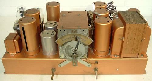
Chassis after rebuilding. All new caps, wires inspected and replaced where necessary, and new grounded line cord installed.

regards,
Bob Putnak.
eBay ID = rjputnak