
The “classic” cathode emission tube tester comes in many makes and models. Since they share the same circuit design, I have consolidated previous discussions into one article.
Among the popular USA models are:
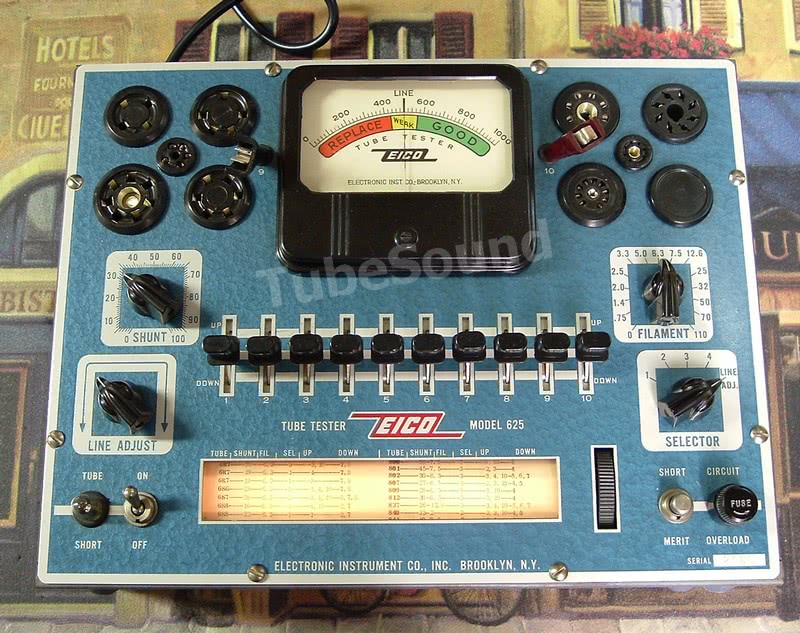
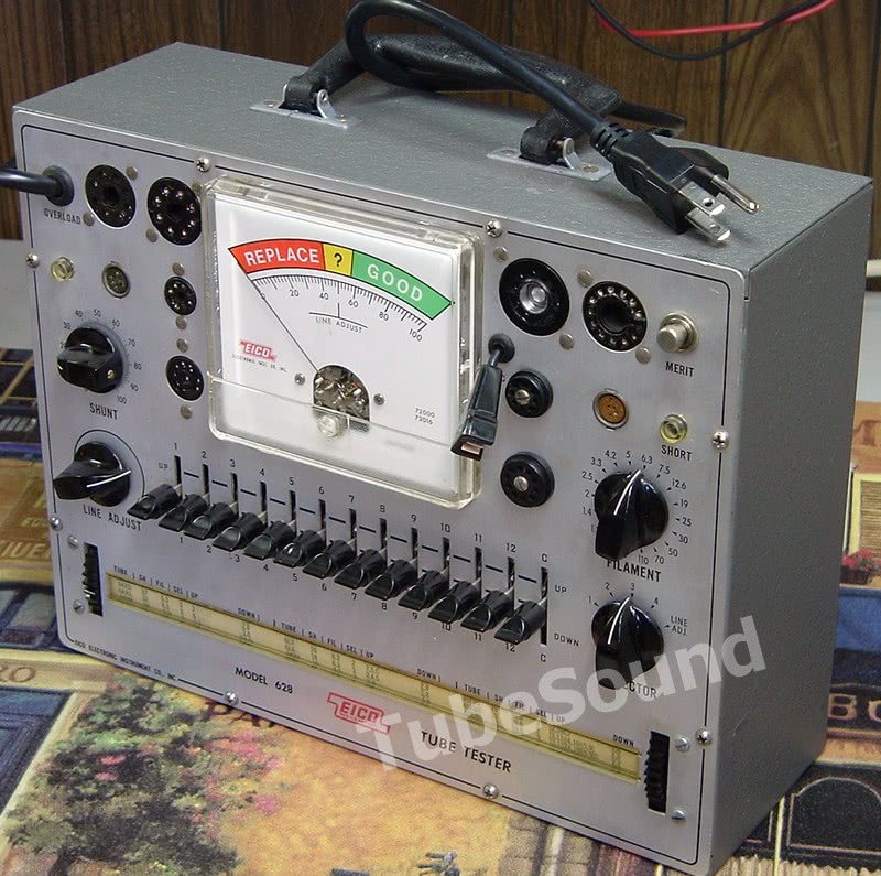


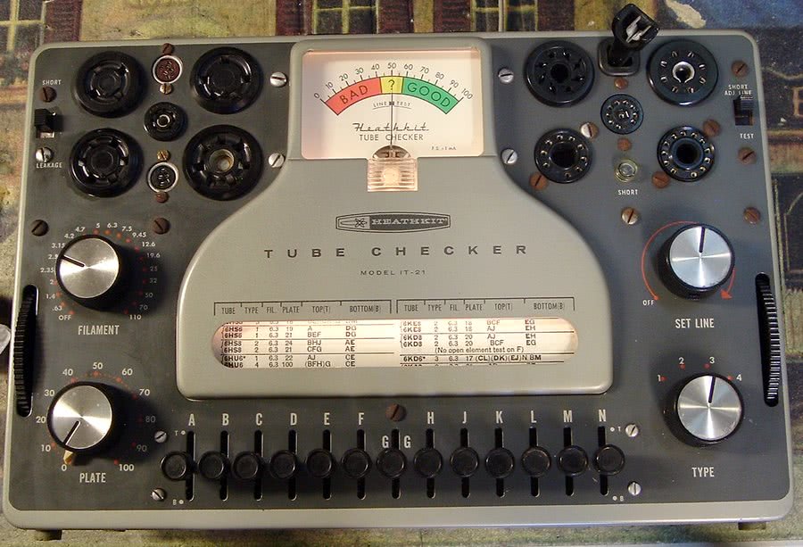
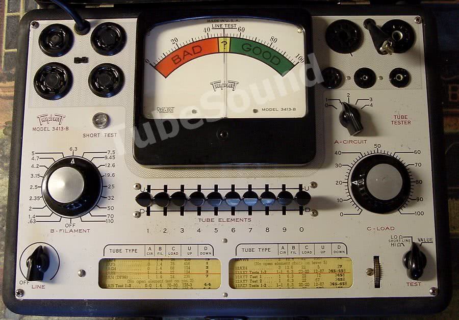
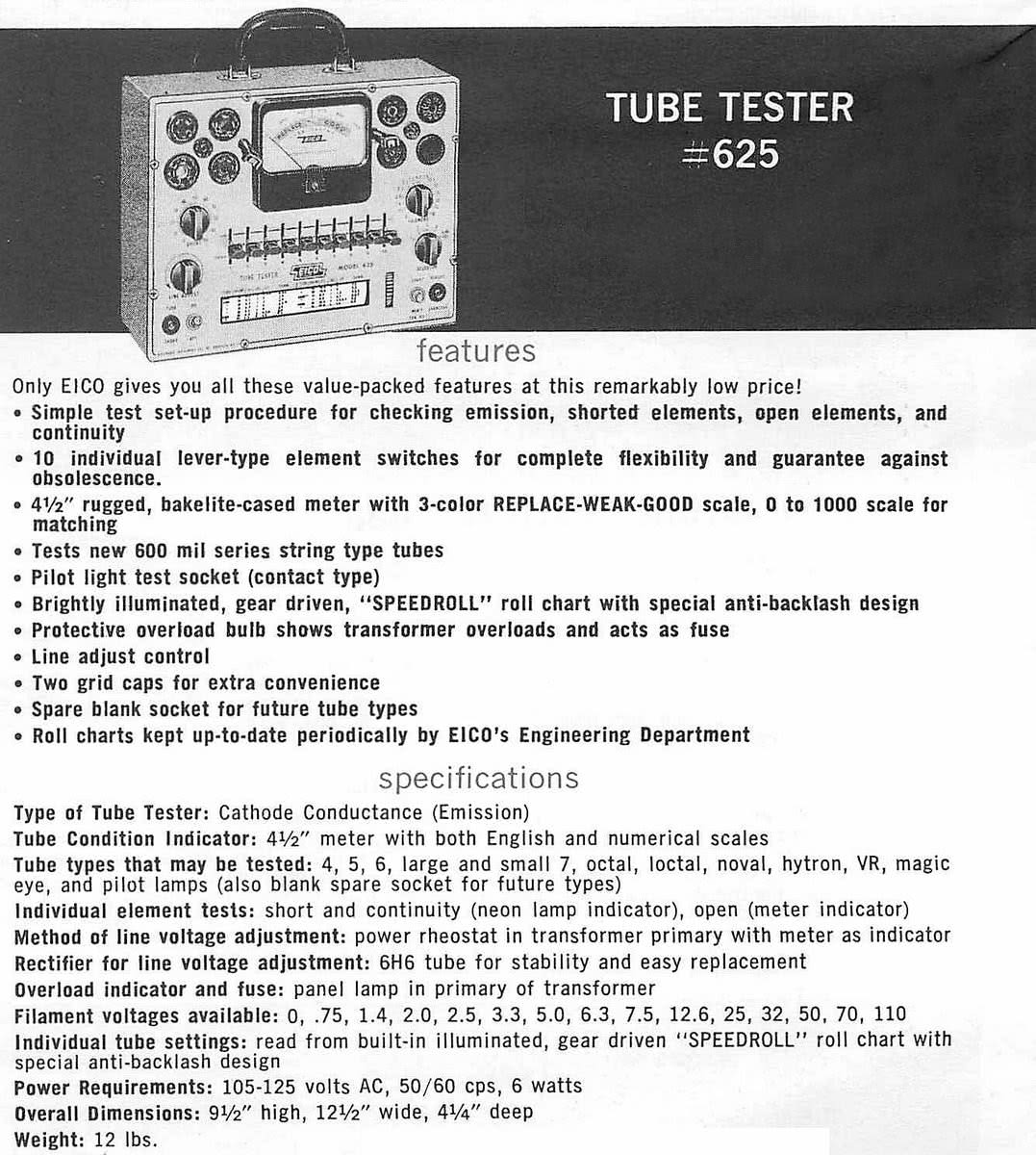
Eico 625, Eico 628, Knight 600-series (83YX142, 83YX143, 600, 600A, 600B, 600C), Triplett 3413, Heathkit TC-1, TC-2, TC-3, IT-17, IT-21.
Other makes/models exist that share this same base circuitry, and the schematics are mostly interchangeable and can be used to repair their cousins. Any differences are very minor, such as different socket configuration, fixed transformer primary windings vs line potentiometer, slight series resistor differences, or slightly different leakage sensitivity.
Many of these testers were supplied as a kit to be self-assembled — Eico, Heathkit, Knight.

remastered paperwork package for Knight 600-series, consisting of construction manual, operating instructions, and two setup chart supplements,
all for $15.99 free ship USA

TUBE DATA CHARTS
Since the test circuit for all these models is identical, you can interchange the setup data charts with each other. This is a great benefit, since between all of those models, you have access to a very large pool of test data for thousands of tube types.
In some cases, the “Tube Elements” are indexed with letters (A, B, C…) instead of numbers (1,2,3…), and likewise the “A-Circuit” is indexed with letters A,B,C,D instead of 1,2,3,4. Common sense allows you to equate A=1, B=2, etc. Very simple.
Each manufacturer appears to have created their own test data, and the test configuration is often significantly different. For example, the Knight charts are unconventional in that they focus on the plate and/or screen grid, often ignoring the control grid, and mostly use the 250V transformer winding for the emission test. The other manufacturers used a more conventional emission-test approach; they focus their charts on the control grid and use the 30V transformer winding.
The upshot is that the setup chart that you use will have a large bearing on your test result. Since many of these charts are available, it can be useful to have a chart from Eico, Heathkit, and Knight, and see what fits your needs best.
Service
Remove the chassis from the case, remove the roll chart, and give the unit a thorough cleaning (inside and out), and dry with a powerful garage air compressor. Do not allow either the meter or transformers to get wet. Clean the roll chart window. If the roll chart does not roll smoothly, very carefully lubricate. Check that the meter needle is indexing at zero (adjust setscrew accordingly).
Replace any old rubber grommets that hold “pilot” lamps because they are usually brittle, and when they fail, will cause shorts to the chassis.

Clean the lamp sockets. Test/clean or replace the lamps.
When servicing any kit-supplied tube tester (Knight, Eico, Heathkit…), you need to (1) check ALL solder joints, including at the tube socket pins, and (2) follow the schematic and check all wiring. Do not assume that the original owner wired the unit properly. Wiring mistakes will be found on many kit-built units.
Inspect the AC line cord and rubber feet. Replace if necessary.
Replace the 0.1 shorts capacitor. Check all resistors for accurate values.
Meticulously clean all switches, potentiometers, and tube socket pins.

The Load control potentiometer can usually be opened by removing the knob, remove the nut and drop the pot from the chassis, then remove its rear cover.

Treat the inside of the Load control with Deoxit, work the pot back and forth, then reinstall.
Install socket savers to protect original sockets.
Need a pair of new socket savers to protect your tube tester sockets? Buy a pair of new socket savers: 1 each SS-8 (octal) and SS-9 (9-pin-miniature). $29.99 free ship USA
Line Calibration
(Note: the diode symbol is reversed in some of the schematics, so be aware of that mistake. If you replace the diode and the meter deflects backwards, swap the diode around.)
For models that have fixed primary windings selectable by a “Set Line” switch
Heathkit IT-17 and IT-21 — you can read the schematic for transformer primary windings that should cause the meter to read exactly at “Line”. For example, if you set your variac to 135.0 vac, the first position after OFF is for a 135 vac input, and therefore in that position your meter should be reading “Line”. At maximum clockwise position of the Line control, a 95 vac input will cause meter to read exactly “Line”. The 1000 ohm resistor in series with the diode must be replaced with a calibration control (variable resistor) to achieve best accuracy. This is R9 on the IT-17 schematic.
For models with a Line potentiometer, there are several approaches to Line calibration. The first two approaches are quite similar and will yield similar results.
Line Calibration approaches:
(1) one approach is to read the schematic to learn the operating range of instrument, examining the transformer primary, such as 100v-125v, as shown on the Eico 625 schematic. Hence, at minimum CCW position of the “Line Adjust” pot, an input voltage of 125 vac will cause the meter to read LINE, and at maximum CW position of the “Line Adjust” pot, an input voltage of 100 vac will cause the meter to read LINE. Other units will show an average input voltage, such as 115 vac, and in that situation the operating range of the instrument is assumed to be 100-130.
(2) an alternative approach is to calibrate based upon one of the transformer windings. For example, the Knight manual suggests that the line is properly adjusted when a known accurate transformer winding, the 6.3 filament winding, reads 6.3 on your multimeter and the tester meter reads LINE, under no-load conditions. The secondary windings can be used as reference if they are known to be accurate.
(3) a third approach that some people use is a variation of #2, except that they calibrate the line so that one of the filament windings that they use most often, usually the 6.3 winding, accurately reflects LINE under the load of chosen tube (often a 6L6 or 6V6). This means that they place a 6L6 or 6V6 tube in the machine to draw filament current, then perform the LINE adjustment.
The Triplett factory procedure used this procedure, although at a much lighter load. The Triplett procedure called for an 8-ohm load on 5.0vac to read “LINE”. That is a fairly light load (625ma), and certainly much less than the loads you would have from a 6L6 or 5U4. So, using a 6L6 may seem practical, but it will cause all readings to be higher than methods (1) or (2), or the 625ma load from the Triplett factory procedure.

Line Calibration controls
For the Eico 625, the 95K resistor in series with 6H6 plates must be replaced with a calibration control (variable resistor) to achieve best accuracy. Similarly, the 6H6 tube can be replaced with a diode for stability and repeatability.
Heathkit TC-1 / TC-2 / TC-3 / Triplett 3413, the 1200 ohm resistor (1750 ohms, Triplett 3413A) in series with the diode can be replaced with a calibration control (variable resistor), or alternatively, the 75k series resistor can be tweaked to achieve calibration. The old diode can be upgraded to a modern silicon.
Heathkit IT-17 / IT-21, the 1000 ohm resistor in series with the diode can be replaced with a calibration control (variable resistor), or alternatively, the 75k series resistor can be tweaked to achieve calibration.
Triplett 3413-B, R10 is the Line calibration control. This must be set last, …AFTER performing the Triplett emission calibration procedure first.
Shorts and Leakage Test

Shorts Test can be checked by using a test socket and jumper wire to short two pins.

Leakage Test can be checked by using a resistor (instead of jumper wire) to simulate leakage.

Notice more dim response from the Neon Light, which is proper. The more leakage, the brighter the Neon will illuminate.
[More leakage = closer to Short].
Triplett 3413-B, this model has separate shorts and leakage sensitivity tests. Proper calibration is that the low sensitivity test should light the lamp somewhere between 250k and 500k, and be not illuminated for leakages above 500k. High sensitivity calibration will detect leakage at 2meg, and not be illuminated above 2.5meg. When servicing, the low sensitivity is calibrated first, then the high sensitivity is calibrated second. The easiest way to do this is to remove the old factory resistors R2 and R15. Attach 350k resistance between any two socket pins, setup to test low sensitivity shorts, attach a resistor decade where R2 was, and dial in the value that just barely glows the lamp. Recheck that 200k leakage detection is reasonably bright, and 500k leakage is not detected. Solder in the resistance that you discovered. Repeat process for high sensitivity (where R15 was) and using 2meg leakage simulated.
Emission calibration
For most models, the emission calibration is best set with calibration tubes for best overall performance.

Due to the basic design of the circuits, there is a natural variance in readings from model to model and you cannot achieve unit-to-unit consistency (nor is necessary for the purpose of the instrument). If any range needs tweaked, it is done via the shunt resistors (not the “load” current limiting resistors). From a useability standpoint, emission test results are often best compared vs testing a new tube of same type, and not solely relying on the meter scale.
The Triplett 3413 models do have a specified factory calibration procedure. R16 is the emission calibration pot, and is set using Range 1 as the basis. Ranges 2 and 3 are tweaked via adjusting shunt resistors (R5 and R6) respectively. In general, once Range 1 cal is set, it is less common that R5 and R6 will need to adjusted on a Triplett.
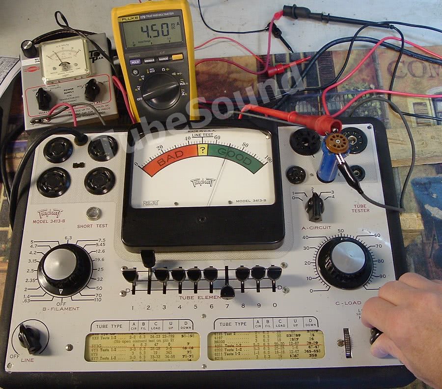
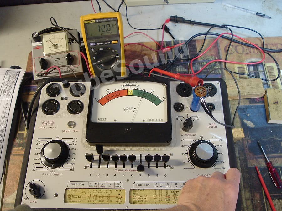
Using 3413-B as an example:
- range 0 reads 1.05ma DC at “70” on the meter, load control @ 50
- range 1 reads 1.4ma DC at “70” on the meter, load control @ 50
- range 2 reads 4.5ma DC at “70” on the meter, load control @ 50
- range 3 reads 12ma DC at “70” on the meter, load control @ 50


Conclusion
The classic emission tube tester is a solid choice for several reasons. The circuit is easy-to-use, easy-to-maintain, and easy-to-operate.

This Emission test circuit was an “industry-standard” and was popular enough to be used by many different top-shelf manufacturers including Triplett, Eico, Heathkit, Knight, and small variations of the same theme were built by Precision Apparatus and others. While an Emission circuit is much less sophisticated than a Mutual Conductance test method, Emission does a good job at determining whether a tube likely is good or bad, and “good or bad” is what most technicians want to know.
For people with more sophisticated needs, there are certainly more complex (and much more expensive) tube testers available. For everyone else, this combination of simplicity, reliability and price are among the many reasons why these testers were popular among radio/tv/amp technicians in the “old days” and remain popular in use today.
And for those of you who read asinine opinions about how useless emission testers are, here is a video from Mr. Carlson — one of the world’s most knowledgeable electronics experts — using a classic Heathkit IT-17 emission tester and singing its praises:
So, next time you read chat forum drivel posted by some crackpot who is denigrating emission tube testers, ask yourself why the famous Mr. Carlson uses one and speaks favorably about it.
And of course, all of these models use the same basic circuitry, so any model in my article is equivalent from a testing methodology standpoint. There is nothing different about the IT-17 (used in Mr. Carlson’s video above) except that it has more sockets; the testing methodology is exactly the same.
regards,
Bob Putnak.
eBay ID = rjputnak