This article will discuss repair and calibration of the Jackson 561 tube tester. High voltages are present, repairs should only be attempted by a qualified technician. Copyrighted, all rights reserved.
Introduction
The Jackson 561 appears to be a rare (uncommon) model. Very little documentation exists, and I have seen only a small number of them for sale.
The model 561 is a combination of the Jackson 634 and the 648. Photo below shows Jackson 561 (right); Jackson 648A (left).

If the 634 and 648 mated, the 561 would be its offspring. It shares the following characteristics from the 648: (a) the same meter, (b) variable leakage control, (c) color scheme, and (d) case design. From the 634, it shares (a) the same test method (which Jackson calls “Dynamic Output”), (b) Shorts Test control, (c) lack of a Noise test, and (d) function control layout. In fact, the 634 tube setup chart can be used (with slight modification) with the 561, as explained later.
Model 561 dimensions: 15 x 12 x 6 (inches), weight: 11.5 lbs. In comparison, the 648A weighs 18-lbs, and 634 weighs 9-lbs.

Tube Setup Data Information
As previously explained, model 561 shares the same “Dynamic Output” test method and Control Layout with model 634. There are two minor differences: (1) model 561 has “Circuit X” — a set of lockout switches that Open circuits to individual tube pins, which model 634 does not have; (2) model 561 has the Plate Control indexed from 0 to 50, whereas model 634 indexes the Plate Control from 0 to 100. The “Circuit Y” control on the 561 is the equivalent of “Circuit” control on model 634.
Therefore, with slight modification, you can use the tube setup chart from model 634 with your 561. This is very useful because the 561 roll chart does not provide data for most antique 4-pin & 5-pin types. To use the 634 chart, you must (1) Leave Circuit X in the Normal position, and (2) divide the Plate Control setting in half. Very simple.
Let us use a #10 Power Triode as an example. This is one of the few early 4-pin triodes that are listed on both the 561 roll chart and the 634 chart.
- 561 roll chart: “7.5 Fil., Circuit X = normal, Plate = 18, Circuit Y = 2, Z = LS”
- 634 chart: “7.5 Fil, Plate = 36, Circuit = 2, LS”
Obviously, the only change was the plate control being double on the 634. This is common sense when you remember that model 634 indexes the Plate Control from 0-100, instead of 0-50.
Another quick example, consider Diode #1 of a #83 rectifier.
- 561: “5.0 Fil., X = Normal, Plate = 9, Y = 2, Z = S”
- 634: “5.0 Fil., Plate = 18, Circuit = 2, S”
Therefore, the pattern is obvious. One unique setup data quirk is that a 6L6 has slightly different setup on the 561 than the 634, but when tested under the 634 setup data, the results are actually slightly more accurate, so either are acceptable.
Roll Chart
The 561 roll chart has an excellent selection of audio tubes listed, including listing data for popular tubes such as 2050, 5687, 5842, 5879, 6146, 6550, 6973, 7027, 7189, 7199, 6CA4, 6BM8, 6CA7/EL34, 6BQ5/EL84, etc. This is only a small list; the chart is quite comprehensive in my opinion. When used in combination with the Jackson 634 setup data for the early 2-digit and 3-digital tubes, such as #50, 01A, 1V, #10, 2A3, #15, #19, #26, #27, #45, 71-A, 807, …etc…, you have strong coverage of most antique and popular audio tube types.
Sockets
Model 561 has the following sockets: 4-pin, 5-pin, 6-pin, 7-pin large, 7-pin miniature, Octal, Loctal, 9-pin-miniature (aka – noval). To accommodate future expandability, there are two spots available to add additional socket types. Missing are “newer” socket types of Novar, Compactron, Magnoval, and Nuvistor.
Technical, Service, and Calibration Information
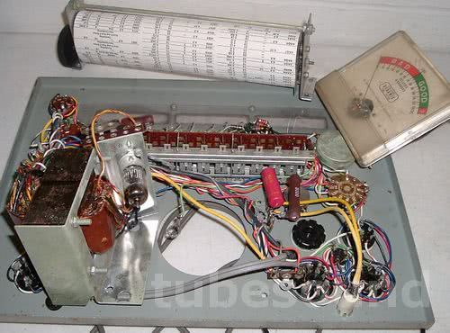
As always, start by removing the chassis from the case, remove the meter and roll chart, give the unit a thorough cleaning (inside and out), and dry with a powerful garage air compressor. Reinstall the meter, and check that the meter needle is indexing at zero (adjust setscrew accordingly). Remove and clean the plastic roll chart window. If the roll chart does not roll smoothly, very carefully lubricate. Even the slightest excess lubricant will absorb into the paper roll, which you want to avoid. Do not reinstall the roll chart until you are ready for final reassembly.

Replace the 0.1 capacitor. Check ALL resistors for accurate values. Resistors that cannot be checked in-circuit must be removed from circuit, checked, and reinstalled or replaced. All switches and potentiometers (especially the Plate control) must be cleaned with Deoxit. All Circuit X switches, and all Circuit Z buttons, must be treated with Deoxit and vigorously worked. Clean every socket pin.
Here is a photo where I removed the 561 Plate control, and will treat the potentiometer with Deoxit through the small opening as shown with the arrow in the photo. Work the Plate control vigorously after treating with Deoxit, then reassemble. This completes the preliminary work necessary for calibration.

Remove the 6C4 tube, clean its pins, test this tube on another tester. Replace tube if its emission is not strong. Be sure to test for shorts and leakage.
The 561 uses a different Line Control circuit than its brothers. The “Line” position on the meter will not set immediately when the Tester is powered-on, because the 6C4 tube must reach operating temperature.
Line Calibration
An interesting observation is that all line switch positions, except for one, actually occur two times in a row. In each instance, the duplicate switch positions are simply jumped together. The only explanation for this implementation is that 12-position switches were rather common, so it was probably more cost effective to use a standard 12-position switch instead of buying a 7-position. To fill all 12 positions, obviously they needed to double some of them up. A quick glance at the schematic shows this peculiar implementation. Most users would probably think each position is giving them some different adjustment. This is not the case.
I have modified the Jackson 561 schematic [HERE] to better reflect the circuit and correct a few mistakes. Here are a few notes that I have observed about the circuit:
- The original schematic listed the line voltages as 107,110,113,116,119,122. The optimal input voltages are actually 1-volt higher — an insignificant difference, no doubt — but achieve most accurate machine operating voltages at line input of 108, 111, 114, 117, 120, 123.
- Anticlockwise from OFF, the voltage positions are: 108-108, 111-111, 114-114, 117-117, 120-120, and the 123 position is the only one that is not “doubled-up” on the switch. That said, I have seen another 561 where the line switch was wired with 107/108 as the single position, and the remaining positions doubled-up 111-111, 114-114, 117-117, 120-120, 123-123. So be aware that both schemes were used.
- Line calibration (assuming switch wiring described above) is performed at first clockwise position from OFF using a monitored line input voltage of either 122v, or better yet 123v. Adjustment via R11 variable resistor so that meter reads LINE for a 123v input line voltage.
- filament position “117” is actually 100 volts
- filament position “70” is actually 75 volts
- filament position “35” is actually 32 volts
- filament position “3” is marked on the faceplate as “3.0”, but is marked as “3.3” on schematic and measures closer to 3.2v.
- remaining filament positions have close accuracy
- “S” test button will ideally measure 210.0 volts plate-to-cathode
- “Q” and “R” test buttons will ideally measure 110.0 volts plate-to-cathode
Shorts and Leakage Test
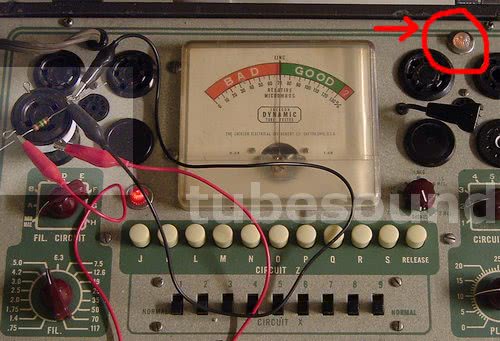
Using a test socket and jumper wire to short two pins, you can easily check proper Shorts Test functionality.
(Jackson 561 shorts test working properly — notice very bright Neon Light as circled in photo)

Using a 1-Meg resistor instead of jumper wire, you can verify Leakage Test functionality. Notice more dim response from the Neon Light, which is proper. The more leakage, the brighter the Neon will illuminate. [More leakage = closer to Short]. As you turn the variable leakage control counterclockwise, the Neon Light will dim and eventually not light. This is correct behavior. As you turn the Leakage control clockwise, the glow should become brighter. If your results are materially different, you need to recheck this circuit.

Performance: Tube Test Photos
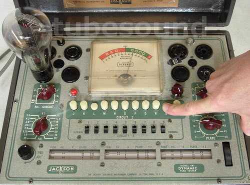
(Testing a Cunningham CX-350 Globe #50 Triode tube. Setup data obtained from the 634 setup chart variation as discussed above.)


(Testing a Western Electric 5842; notice test results virtually identical to 648A, as marked on tube box, approx 01% test result difference)

Final Thoughts
The Jackson 561 is a quality tube tester, with durable construction and versatile configuration. It would be an excellent choice for most people, including antique radio collectors, most guitar tube amp guys, and most tube audio enthusiasts. A good combination of medium size, excellent build quality, dependable design, ease-of-use, and the ability to test most popular antique tubes and most newer tubes (with the exception of Compactrons/Novars/Magnovals, which are mostly used by Ham Radio operators, and also nuvistors). The variable leakage control is also a welcome feature.
regards,
Bob Putnak.
eBay ID = rjputnak
Miscellaneous Notes:
How Long Does a Calibration Last?
This is an impossible question to answer, but I can explain which factors most influence the calibration.
The condition of the 6C4 tube directly relates to the accuracy of the Line Control Calibration. As the 6C4 tube ages, or develops a defect, the Line Control will become inaccurate. This will be the most common source of inaccuracy after a complete calibration has been once performed.
Next, component failure could occur. Most likely this situation would be a resistor(s) changing value. Assuming diligence in your restoration, this is a less-likely situation.
Finally, continuity issues relating to the switches/buttons and sockets. At a minimum, you should clean switches and sockets at least once a year (more often if you are a power user) and treat them with Deoxit. This is good practice and should be considered part of regular maintenance.
Reduce the wear on your tester sockets — Get in the habit of never testing tubes with dirty or rusty pins until you have completely cleaned the tube pins first. This will also increase the accuracy of your tube testing, because dirty or rusty tube pins can significantly affect the accuracy of the test result.
© 2008. All rights reserved.
