
This article discusses the solid-state B&K 607 / 667 tube testers. Both models use the same tube setup data book, and therefore both models are functionally equivalent. Model 607 will be example shown in this article. Electrical voltages are present, repairs should only be attempted by a qualified technician. Copyrighted, all rights reserved.

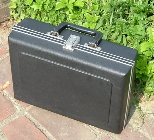
This series was B&K’s clone of the Sencore Mighty Mite TC162. While the circuits are not 100% identical, they are close enough to be considered functionally identical. The B&K 607 weighs slightly less than 6-lbs (without setup book or manual), and size dimensions are: 34 cm L x 24.5 cm W x 11 cm D. The case folds open and easily accommodates a full size 8.5 x 11-inch setup chart and service manual as shown in the photo above.

Remastered paperwork package for BK 607, which consists of manual, schematic, and modern tube data setup chart, all for $13.99 free ship USA.

Remastered paperwork package for BK 667, which consists of manual, schematic, and modern tube data setup chart, all for $13.99 free ship USA.
Need a pair of new socket savers to protect your tube tester sockets? Buy a pair of new manufacture socket savers: 1 each SS-8 (octal) and SS-9 (9-pin-miniature). $29.99 free ship USA
B&K describes the functionality as:
As a direct comparison to the Sencore TC162 Mighty Mite:
- Both are solid-state design
- Both use Cathode emission test method, and use the same 9 Voltage/Load combinations.
- With a little common sense, the Tube Setup Chart Books can be used interchangeably. There does appear to be one difference of opinion regarding the suppressor grid. I notice that the Sencore data book locks-out the suppressor grid in many instances when B&K does not (example, pin 8 of a sweep tube such as 6LQ6, 6JF6, etc is locked-out in the Sencore data book, whereas it is left in circuit during the emission test as setup by the B&K chart). Since the test method is cathode emission, this difference in opinion should not affect test results, nor do I remember any times where it has. From a philosophical perspective, the B&K approach is more true to the purpose of the lockout switches — they are meant to lock out internal shorts from being detected (example: pins 2 and 6 inside a 6LQ6 sweep tube are both connected to the control grid. One of these two pins must be locked-out, otherwise a false short will be detected.) Since Pin 8 of a 6LQ6 is not internally connected to any other pin, I see no valid reason for it to be locked-out. Regardless, either test data book would yield appropriate results.
- Both units have industry-best grid leakage detection, and calibrate the grid leakage with a 100-Meg resistance.
- Both units have 10 lockout switches. (These lockout switches were the only difference between the Sencore TC162 and older Sencore TC154. The TC154 did not have lockout switches.)
- Tubes available for testing are “newer” tube types: 7-pin miniature, 9-pin miniature, octal, nuvistor, novar, compactron, magnoval. Obviously the very old antique tube types (4-pin, 5-pin, etc) are not testable because there are no sockets for them, nor any test data in the setup charts.
- Both units automatically damp the panel meter when powered off. This protects the meter when carrying the tube tester.
Minor Differences:
- B&K has a pair of 7-pin and 9-pin tube pin straighteners built-in, a nice convenience.
- Sencore TC162 has a potentiometer to more easily calibrate emission results; the B&K does not.
- TC162 has 14 sockets; the B&K 607 has 11 sockets. The B&K does not have a loctal socket.
- The B&K 607 tests for shorts automatically as the Selector knob is rotated; the TC162 must be manually placed into “Shorts” test.
- The TC162 has a “meter zero” control, whereas the B&K does not use this manual adjustment.
- The B&K has a potentiometer to easily calibrate the Shorts sensitivity; the TC162 does not.
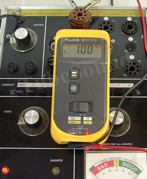
- The B&K uses approx 100 vac during Shorts Test; the Sencore uses 34 vac during Shorts Test.
- The B&K shorts detection is more sensitive (1-meg); the TC162 detection is 300K.
- A few other very insignificant circuit differences — for example, one unit uses transistor 2N5457 and the other unit uses 2N5458, etc. None of these small circuit differences are important.
Servicing the B&K 607 / 667
As always, start with the fundamentals. Check and replace all non-spec resistors. Check (or replace) all capacitors. The electrolytic capacitors originally installed in these units are often higher capacitance that listed on the schematic. The parts list shows C4 @ 150 µF and C5 @ 160µF. The schematic lists both as 160 µF. In most units, the cap installed at C4 was 150µF and C5 is 220µF. Obviously, anything 150µF or a little higher is fine. Treat all sockets and switches with Deoxit. Check continuity between all socket pins and proper continuity of Lockout switches. Check secondary transformer voltages (filament voltages and Load voltages). Check circuit board voltages as marked on the schematic. If meter has suspicion of being defective, remove and test (scale 0 – 1 DC mA).
Cathode Emission Test
The cathode emission test method places AC voltage between the control grid and the cathode of the tube being tested. (For rectifiers and diodes, the test method places AC voltage between the plate and cathode.) The tube rectifies the AC voltage into DC; a load resistance (comprising either one resistor, or a series of resistors) is placed in series with the cathode to develop a pulsating DC voltage. The Load switch selects a predetermined voltage-load combination (one of 9 different selections) that is appropriate for the tube, and the resulting cathode current is measured and output to the panel meter, where the user can easily read the test result as Bad, Questionable, or Good. Note that the 3.9 meg resistor (R19) is printed as 1-meg on schematic (488-089-9-001B)
The voltage-load combinations (control grid to cathode) on the B&K are as follows:
- Load A: 40 VAC, 140 ohms
- Load B: 40 VAC, 300 ohms (140Ω + 160Ω)
- Load C: 30 VAC, 300 ohms (exact same as Load B; no additional resistance)
- Load D: 22 VAC, 520 ohms (140Ω + 160Ω + 220Ω)
- Load E: 22 VAC, 740 ohms (140Ω + 160Ω + 220Ω + 220Ω)
- Load F: 22 VAC, 1420 ohms (140Ω + 160Ω + 220Ω + 220Ω + 680Ω)
- Load G: 22 VAC, 11420 ohms (140Ω + 160Ω + 220Ω + 220Ω + 680Ω + 10KΩ)
- Load H: 40 VAC, 19620 ohms (140Ω + 160Ω + 220Ω + 220Ω + 680Ω + 10KΩ + 8.2KΩ)
- Load J: 40 VAC, 41620 ohms (140Ω + 160Ω + 220Ω + 220Ω + 680Ω + 10KΩ + 8.2KΩ + 22KΩ)
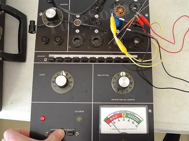
Load Voltages: Load voltages are easily checked by configuring the machine to test a 6L6 (do not insert a tube). Using a test socket in socket 1, measure the AC voltage between pins 5 and 8 while depressing the Quality button. Be sure to check the voltage at each Load switch position from A through J.
Of course, actual AC voltages will differ based upon input line voltage to the transformer primary. Typically, they will be a little higher (such as 43 VAC at Load A, etc.)
Load Resistances: Notice that the load resistances are in series, therefore each previous load affects all of the following loads (except for Load C, which has the same load as Load B). For example, Load F’s 1420 ohms of resistance consists of: 140 ohms from Load A + 160 ohms at switch position B + 220 ohms at switch position D + 220 ohms at switch position E + 680 ohms at switch position F. Hence, it is easy to see that if any counter-clockwise load resistor is faulty, all clockwise loads will be incorrect. Therefore, any tweaking or recalibration of these load resistances must be performed starting at Load A and working clockwise.
Load resistances can be “fast” checked very easily. With unit powered off, using the same test socket as explained above, set the Load switch to position J and measure the resistance between pins 5 and 8 while depressing the Quality button. This is not a precision test because you are testing through the test entire circuit (not just the load string), but the resistance will be reasonably close to the load posted at Position J (which, as explained, includes all subsequent loads, thereby testing the entire string in one fast step).
Grid Leakage Test
Like the Sencore Mighty Mite series, the super-sensitive grid leakage test is probably the best attribute of the B&K 607. As the electron emitting material of cathode is worn away from age, some of the cathode material that has evaporated gets deposited on the grid. This causes the grid to incorrectly emit electrons – “grid emission”. This causes the grid to draw current and be more positive than it should be, thereby negatively affecting the circuit.
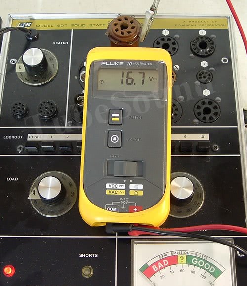
The tube under test has positive DC voltage (approx 16.7 vdc) applied to all elements except the grid, and the grid is biased beyond cutoff. (This DC voltage is measured in reference to (-) of electrolytic capacitor). If grid leakage is present, current will flow from grid to plate of the tube through the 8.2 meg resistor (R20). This voltage is amplified by the solid-state amp, causing a deflection of the panel meter. The user then reads the Grid Emission scale on the meter to see whether the leakage is within the green-acceptable range or the white reject range.
The 100 megohms reject sensitivity is super-sensitive. Most tube testers will not measure leakage anywhere near this sensitive. The Sencore TC162 manual does a good job of explaining this benefit. “A lower sensitivity of 2 to 5 megohms found in many tube testers may eventually reject the tube but not during the time that it is being tested because tube heat causes the leakage to increase with time.” In other words, unless the tube was very hot and operating in-circuit, and then immediately inserted into a tube tester, it is unlikely that other testers would find the leakage. Since most tubes are tested “cold” (meaning not removed hot from circuit), you can readily see the advantage of the Mighty Mite leakage test. Continuing from the manual: “On some tubes, leakage may not reach this low level and the checkers with lower sensitivity will not find the ‘tough dog’ tube.”
The B&K service manual explains that while not all circuits will be severely impacted by grid emission, “…applications such as RF Amplifiers, IF amplifiers, etc… any grid leakage is cause for rejection.” As previously noted, this B&K will find those tubes with grid leakage at 25 megohms, 50 megohms, …100 megohms that are negatively affecting your circuit — most other tube testers will NEVER find this leakage. This is not the level of performance that most serious tube enthusiasts are satisfied with — they want to know when the tube is negatively impacting performance.
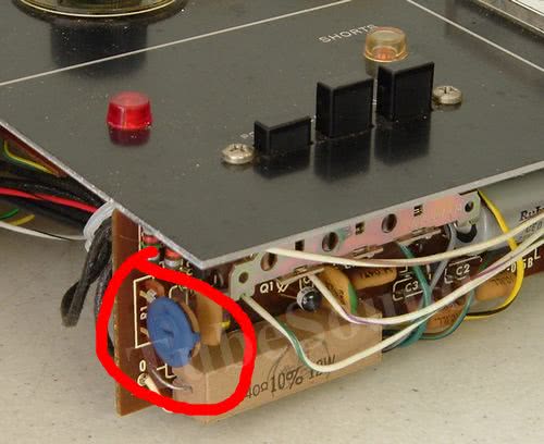
The grid leakage is calibrated by connecting 100 megohms between pins 1 and 9 of socket 6. At selector positions 1 or 9, push the leakage button and adjusting R16 (10k) trimpot so that the meter reads on the division between Green and White on the grid emission scale. The service manual calls this the “white” pot, but I have found it to be blue on some models. (On models where R16 is blue, the other pot will be white. In other words, the opposite of the color scheme explained in the manual).
It is important to note that Grid Leakage adjustments will significantly affect the emission test; therefore, grid leakage adjustments must be made before any Emission adjustments.
Shorts Test
The Shorts Test selects one tube element, and all other tube elements are tied together. The test places approx 100 VAC between this one selected element and all other elements. If the selected element has a short (or extreme leakage up to 1 megohm) to any of the other elements, the Neon lamp will light. The Neon lamp will just barely glow at 1 megohm, and will glow brighter as the condition approaches solid-short. As your rotate the Selector switch from 1 to 12, all tube elements are compared to each other.

The use of lockout switches ensures that false-positives are not reported, and also 100% ensures that all shorts between elements are detected.
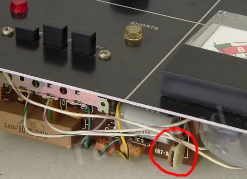
The Shorts test is calibrated by connecting 1 meg resistor between any two pins and the Neon lamp should glow when the Selector switch is rotated to the number of those pins. Per the manual, connect to pins 1 and 9 of socket 6, and at Selector positions 1 and 9 the Neon lamp should just barely glow. (Photo below uses pins 6 and 7 as another example.) Adjustment is made by the turning the R1 (2Meg) trimpot on the circuit board. (The manual refers to this as a blue trimpot, but I have found models where this pot is white, so just look for R1 regardless of color). This test is actually quite sensitive on these units, and you may find that if you calibrate using an new precision 1 meg resistor, if you connect an old 1 meg resistor that has slightly increased in value, the “slightly above 1 meg” resistor may not light the neon lamp. Very surprising how sensitive this is Shorts test is. If the shorts lamp is always lit, recheck C1 (.047 or .05) for defect.

Conclusion
Everything that can be said about the Sencore Mighty Mite can be said about the B&K 607 / 667 series. The unit is functionally equivalent to the TC162. It is lighter weight due to its plastic attache case, but slightly larger in length. The extra length is a benefit when buying updated tube data setup books or a service manual, since the case has a pocket to conveniently house an 8.5 x 11 document, whereas the Mighty Mite case is too small is house an 8.5 x 11 setup book. The Shorts test is automatic as you rotate the Selector switch, and the leakage control is placed more conveniently via push button instead of rotary switch. The grid leakage detection is industry-best. Overall, an excellent choice for anyone working with “newer” tubes, and an excellent compliment to a Hickok or other tester that really does not have the same outstanding grid leakage detection.
regards,
Bob Putnak
eBay ID = rjputnak