
This article discusses repair and calibration of the Signal Corp I-177 tube tester. Serious electrical voltages are present, repairs should only be attempted by a qualified technician. Copyrighted by Bob Putnak, all rights reserved.


Introduction
Model I-177 is a very old US Military dynamic mutual conductance tube tester that was used during World War II years. The War Department Technical Manual is dated August 1944, and the tester calibrated in this article is dated April 1945. The unit is extremely well-built. Due to its age and high signal voltage, the tester is only suited to test the “antique tubes” and military tubes of its era and does not even have a 9-pin miniature socket.

The MX-949A/U socket adapter kit (an extra accessory that expands the capability of I-177 models) provides sockets to test “newer” tubes. That said, the 5.0vac signal voltage of the I-177 tester is not suited for testing many of these newer tubes and can damage small signal tubes or provide less-than-ideal readings. That said, the I-177 does an excellent job of testing the “antique” tubes of its era.

Repair
The fundamentals for starting the I-177 project: all knobs and the meter itself are indexed at zero, check all resistors and potentiometers for accuracy and replace where necessary , replace the 0.1 mfd capacitor, clean all sockets/switches/leaf-switches/pots/rheostat with Deoxit to the extent possible. I would specifically note that the I-177 has 7 carbon resistors. Expect that most (if not all) of these carbon resistors will have increased in resistance and will need replaced. The remaining resistors are either wirewound or precision types, and while they should be tested, it is unlikely that any would be defective. Inspect all wiring (AC power cord, and also each wire connection at every tube socket pin). Remove both bulbs (#81 fuse bulb and neon shorts lamp), clean bulb connections and sockets, reinstall. The #81 fuse bulb must be only a #81 bulb (no substitutes).

Need a pair of new socket savers to protect your tube tester sockets?
Buy a pair of new manufacture socket savers: 1 each SS-8 (octal) and SS-9 (9-pin-miniature). $29.99 free ship USA.

Need a quality solid-state #83 upgrade?
We offer a premium version of the #83 solid-state upgrade that is fused to protect your transformer. $19, free ship USA.
Regarding the internal tubes, each tube must have balanced sections. Recommend that you replace the #83 with a solid-state #83.
The Line rheostat in the I-177 has plenty of adjustment to handle the solid-state conversion. Select a 5Y3gt tube with balanced sections. If you take these two steps upfront, you will not have to worry about making any plate or screen supply balance tests with a scope.
Unless otherwise noted, all tests below will assume the following configuration: A = 8, B = 5, Fil = 6.3, L = 0, R = 0, Shorts Knob in “Tube Test” position. Insert an octal test socket in Socket E. All voltage measurements were taken with a Fluke DMM shunted to simulate a 1,000 ohms/volt meter sensitivity. Shunt resistors used were: 5K for readings 0-5 volts, 50K for readings between 5-50 volts, 250K for readings of 50 volts or higher.
Notice that the “L” pot is known as “English” or “Shunt” on newer Hickok testers. Similarly, the “R” pot is known as “BIAS” on newer Hickok testers. On the I-177, Pots L & R each have a range from 0 – 82 (some people have incorrectly reported the range as 0-80. See page 6 of TM 11-2627 manual to clear up any confusion.)
Calibrating the LINE
All voltages are automatically adjusted when the user sets the Line.
Hickok factory calibration documents instruct that the “Line” is calibrated when a tested Plate voltage of 150 vdc (±2V) will cause the panel meter to read at “Line” mark when the “Line” button is pressed.
Therefore, connect your meter (remember, 1000 ohms/volt sensitivity) to pins 3 (+) & 8(-). Power on the I-177, and after warmup time, press AMPL TEST and measure the plate voltage. Rotate the Line Rheostat until plate voltage tests 150 vdc. Release AMPL TEST button. Press LINE button to check Line calibration. If Line is off, the I-177 uses a Line Calibration resistor (part #74, resistance approx 13 to 17 ohms).

In the tester used as an example for this article, the Line resistor (which was 15 ohms) was slightly incorrect, and required shunting with a 330 ohm resistor, thereby dropping its resistance to approx 14.35 ohms. (And yes, that slight difference was important to calibrate the Line accurately). Note that in this particular unit, parts #74 (Line calibration resistor) and Part #73 were mounted in reverse order from what is shown on page 15 of TM 11-2627 manual. Another possibility is that since the resistors are almost identical value (15 ohms and 14 ohms), and it is possible that the person who wired the unit mistakenly swapped the connections to them. In any event, verify which of those resistors is the meter shunt for the Line test before you blindly adjust the one identified in the war department manual.
Recheck the Plate Voltage, and then recheck the Line again to verify consistent results.
Make sure that both pots are set at zero and perform the following checks:
Verify accurate screen voltage of 130 vdc (±2v) as tested between Pins 4(+) and 8(-) when pressing AMPL TEST button.


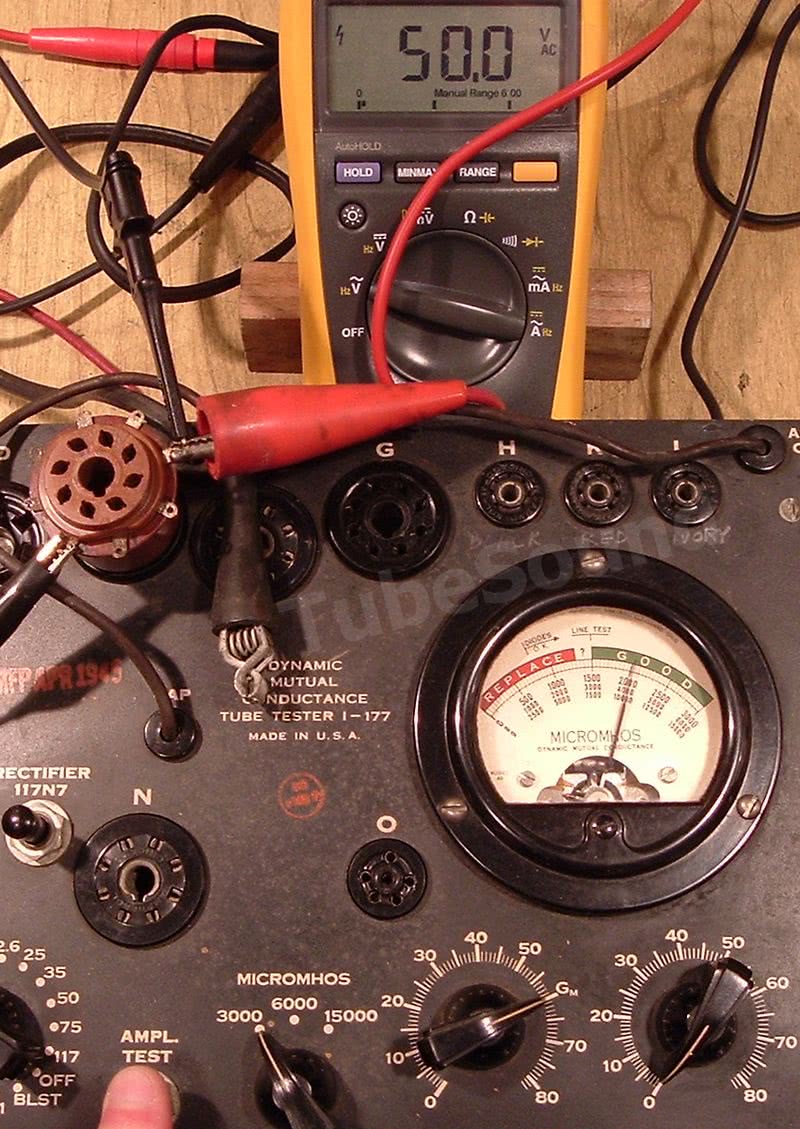
Verify accurate Signal Voltage of 5.0 vac (±0.250 v) as tested between Pins 5 and 8. No button is pressed for this test.
DC BIAS CHECKS & CALIBRATION
Measure DC BIAS voltages between pins 5(+) and 8(-), remembering to use the correct shunt resistors. Set Pot R at zero, verify (0 vdc). Set Pot R at 82, verify (-42 vdc). Set Pot R at 18, verify (-3.0 vdc, ±0.1).


To make a slight adjustment at position 18 for -3.0 vdc, you can reposition the knob on its shaft. (Knob positioning error is the most common issue, as there was “wiggle-room” when you “zeroed” the knob with the faceplate as part of the preliminary steps).
BRIDGE BALANCE TEST
Check meter bridge balance by connecting a large power resistor (10 watt+), 10K resistance, between pins 3 and 8, with Pot L at Gm position. Press AMPL TEST and verify that meter needle remains at zero or within a division or so, which is optimal. Slowly rotate L pot each direction while pressing AMPL TEST, and see that meter needle balance remains. If your balance is bad, your only solution is to remove Pot L (which is a dual section pot) and balance both sections. This requires unsoldering the two halves and tedious work. Not something that is recommended to experiment with as a first-timer. Practice on a junker first.

MUTUAL CONDUCTANCE TEST
Check the Mutual Conductance accuracy. [NOTE: Dangerous test, could cause serious damage and is also a shock hazard if done incorrectly.] Set Pot L at Gm position. Connect an Isolated fixed current source of 10ma between pins 3 & 8. This requires either an ISO-Variac or combination Isolation transformer + Variac. (10ma can be calculated from a 50v source and 5k resistance. Ohms Law: 50v = 5000 ohms x 0.01A). If meter needle deflects downward, swap connections at 3 & 8.
For the I-177, 10ma current source will yield a micromhos score of 2,000 micromhos. (10ma ÷ 5.0 vac signal voltage = 2.0 x 1000 = 2000). This 10ma was chosen so that you can conveniently test all 3 micromhos scales with one current source, including one that will read at the higher end of the meter. 10ma is also low enough to not risk slamming the meter at any range.


Of course, you can use a different current if you want. For example, other calibration documents use a 10K resistance at 50V, thereby choosing 5ma current. Using 5ma, a perfect micromhos score on the I-177 would be 1000. (5ma / 5.0 vac = 1.0 x 1000 = 1000)
Additional Mutual conductance calibration notes:
- If the 3000 range is off a tiny bit, slightly reposition the L-knob on its shaft to correct.
- Precision Calibration resistors for the 6000 and 15000 micromhos ranges are located directly under the micromhos switch. There is one resistor for each range that is switched into the circuit as a shunt. [Photo]
- Resistor Z1 is the calibration resistor for the 15000 micromhos range. (“Z1” as marked on I-177 schematic; part #77 in tech manual). Resistance is approx 17 ohms, may vary slightly from unit-to-unit.
- Resistor Z2 is the calibration resistor for the 6000 micromhos range. (“Z2” as marked on I-177 schematic; part #76 in tech manual). Resistance is approx 70 ohms, may vary slightly from unit-to-unit.
- If either micromhos range reads materially incorrect, adjust its calibration shunt resistance accordingly.
SHORTS TEST
Connect a 250K resistor between pins 5 & 8, thereby simulating a grid-cathode short. Rotate SHORTS knob. Neon lamp should light at shorts position #3.
See my attached chart for complete outline of the Shorts-Test characteristics. This chart shows how each type of short will be detected on your I-177. You may simulate as many Shorts as you want to further test your unit.
Any problems with this test are usually due to R10 (the 500K resistor across Shorts switch) or switch continuity.


GAS TEST
Set pot L at Gm, pot R at maximum (82), micromhos at 3000. Still using your octal test socket in socket E, insert any 6L6 tube that is known to be free of gas, making sure to adjust the Line after tube has had ample warmup time (allow 5 minutes to be sure).

Press GAS 1 and adjust pot R until meter reads 100 micromhos on the 3000 scale. While pressing GAS 1, also press GAS 2 and verify that needle has barely moved (probably less than 1 division). Release buttons, add a 1-meg resistor between pins 5 and 7, which simulates a 1-meg leakage between control grid and heater. Press GAS 1 and GAS 2 simultaneously and verify that meter reads approx 4 or 5 divisions higher than when the 1-meg resistor was not attached. If readings are unacceptable, recheck the 180K resistor at the GAS 2 leaf switch. Disconnect the 1-meg test resistor.

DIODE, RECTIFIER, and OZ4 Test
Assuming that you checked all resistors at the beginning of this process and you made it this far, your diode/rectifier results will be fine. To verify your accuracy:
DIODE:
Set pot R at zero. Check diode test voltage (19 vac) between pins 3 and 8 while pressing DIODE button. Release button.

Connect the cathode (striped) end of a common diode (such as 1N4005 or 1n4007) to pin 8 of test socket. Connect anode end of diode to one end of a 1K power resistor. Connect remaining resistor end to pin 3 of test socket.

Pressing DIODE TEST, meter should read at or near DIODES OK when L pot is at 61. Release button & temporarily disconnect connections from test socket.
RECTIFIER TEST:
Set pot R at zero. Check rectifier voltage (167 vac) between pins 3 and 8 while pressing RECT STD button. Release button.

Reconnect diode/resistor as per above. Pressing RECT STD, meter should read at or near DIODES OK when L pot is at 68. Release button & temporarily disconnect connections from test socket.

0Z4 test:
Set pot R at zero. Check 0Z4 voltage (approx 312 vac) between pins 3 and 8 while pressing TEST 0Z4 button. Release button.

Reconnect diode/resistor as per above, except use a 10K power resistor instead of 1K.
Pressing TEST 0Z4, meter should read at or near DIODES OK when L pot is at 74. Release button, disconnect connections from test socket, remove test socket.

CONCLUSION
Finish your repair by testing a 6L6 tube that is of known quality, and then enjoy your calibrated I-177.


regards,
Bob Putnak
eBay ID = rjputnak