©2011 Bob Putnak.
I am frequently asked how to test voltage regulator (VR) tubes, which are sometimes called “glow regulator” or “glow discharge” tubes.
Few tube testers test VR tubes, and most models that claim to test VR tubes do a worthless job at this task.
- They use AC voltages instead of DC
- the AC voltages are beyond spec
- they offer no ability to monitor or control the operating current
- they provide no ability to test at the minimum and maximum operating range of the tube
- they provide no voltmeter to show the exact voltage drop across the tube.
(Hickok 123A cardmatic, Hickok 752, and Precision 10-40 would be notable exceptions.)
Since the overwhelming majority of tube testers will not test a VR tube properly, we need an answer. As a general observation, if a VR tube lights up, it is probably acceptable. But, that’s not good enough, so how to test a VR tube?
1. The best way to test a VR tube is to try it in the actual equipment, and measure the voltage drop across the VR tube’s anode and cathode.
2. If the first option is not available, you need to create a real circuit and measure the voltage drop across the VR tube at the minimum and maximum operating current as documented in the datasheet.
The datasheet specifications that are most important for VR tubes are:
- “dc operating voltage” or “average anode drop” — this is the voltage drop across the VR tube
- dc operating current range — the minimum and maximum operating current for the VR tube to regulate properly
- average DC starting voltage
Datasheet specifications for VR tubes are not identical for every manufacturer, but all datasheets are close enough to work from, so use whatever receiving tube technical manual that you have available, such as RCA RC-30, GE Essential Characteristics tube manual, or a Sylvania Technical tubes manual.

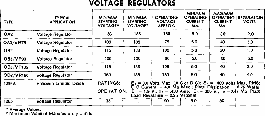
Here is a crib sheet from a Sylvania tube manual that lists several of the most common VR tube specifications.
Popular examples are 0A2 (aka 0A2WA, 6626, 6073), 0A3 (VR-75), 0B2 (0B2WA, 6074, 6627), 0B3 (VR-90), 0C2, 0C3 (VR-105), 0D3 (VR-150).

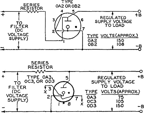
A typical VR circuit is described in the RCA RC-30 tube manual, and you must recreate that circuit using a variable DC high-voltage power supply, series resistor (wattage must be sufficient to absorb voltage drop between PS output and VR tube drop, at maximum current), the VR tube to be tested, and 2 DC voltmeters and 1 DC milliammeter.
One DC voltmeter monitors the DC power supply voltage, which is only needed to monitor the starting voltage of the VR tube. The second voltmeter is placed across the anode & cathode of the VR tube, thereby monitoring the voltage drop across the tube during its range of operation.
The DC milliammeter is placed in the cathode circuit and monitors the operating current of the tube.
The PS voltage is varied between the minimum and maximum operating currents for the VR tube.
NOTE: Lethal voltages and currents exist. Do not attempt without proper training.
Example #1: testing an NOS CBS Hytron 0A2 tube.
The important specs for an 0A2 are 150V average drop (140v-168v, RCA specifications for maximum acceptable); average regulation within the operating range is 2v (6v max, RCA specifications), operating current 5ma-30ma, average starting voltage of 156v (max 185v according to RCA). The Fluke 10 monitors the voltage drop across the VR tube, which is the most important specification. The generic red meter monitors the operating current of the tube, and the Fluke 179 monitors the power supply voltage. My bench power supply and the series resistor are not shown in the photos.


The starting voltage is easily determined by when cathode current starts to flow. This 0A2 started at approximately 152 volts, which was excellent. Voltage drop at 5ma (minimum operating current) was 150.1 volts; voltage drop at 30ma (maximum operating current) was 150.8 volts. Hence, the difference was 0.7 volts, well within the 2 volts average. In fact, this would be considered an excellent 0A2. The RCA datasheet instructs that 6 volts difference would be the end-of-life specification for 0A2, but in practice most 0A2 should regulate within the 2-volt average.
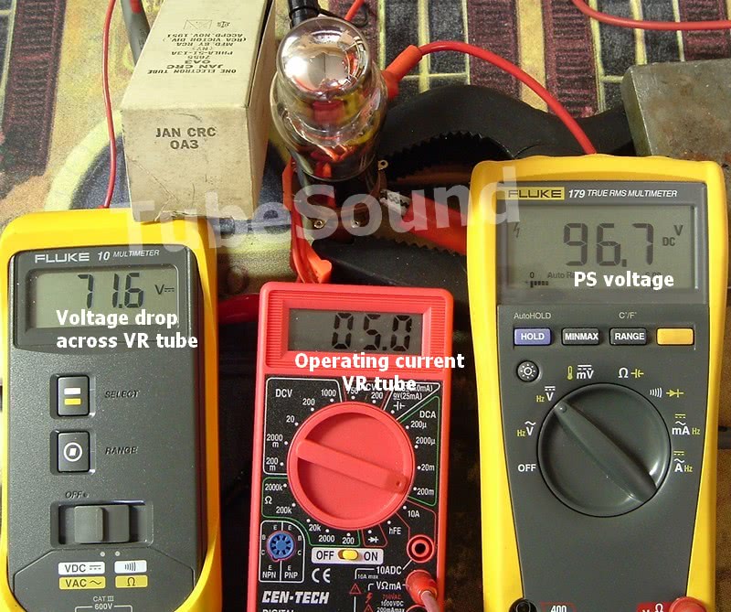
Example #2: testing an NOS RCA JAN CRC 0A3.
A good friend, CJ, asked me to demonstrate testing an 0A3, so the important specs for an 0A3 as listed in the GE ETI-176 tube manual are: 75V average drop; average regulation within the operating range is 5v, operating current 5ma-40ma, average starting voltage of 100v.


This 0A3 started at approximately 90 volts, which was well within specification. Voltage drop at 5ma (minimum operating current) was 71.6 volts; voltage drop at 40ma (maximum operating current) was 76.5 volts. Hence, the difference across the operating range was 4.9 volts, which was almost exactly average (5v average).
Miscellaneous VR tube notes:
- Regulation often improves as the tube is operated more than 20 minutes after starting.
- Most VR tubes are heavily influenced by the absence of light. Some datasheets (sometimes Tung-Sol and Raytheon) will list a specification along the lines of “DC anode supply voltage in darkness”, and the power supply voltage given for operation in darkness is always a significantly higher voltage than is necessary if the glow tube is operated in adequate light.
- Some VR tubes have jumpers internally. The purpose of the jumpers is to disconnect voltage to the circuit if the VR tube were to be removed. It is very unlikely that the jumpers would be defective in a properly regulating tube, but to the extent you feel it is necessary to test the jumpers, you can check them with an ohmmeter.
- Like all tube testing, what is acceptable for your circuit needs may be different from someone else’s needs. A VR tube that is operating slightly outside of parameters, or at the margins of acceptability, may be fine for one circuit but substandard for a different circuit. Like always, context matters.
