Here are a few Q&A’s about a Fisher 500-B receiver:
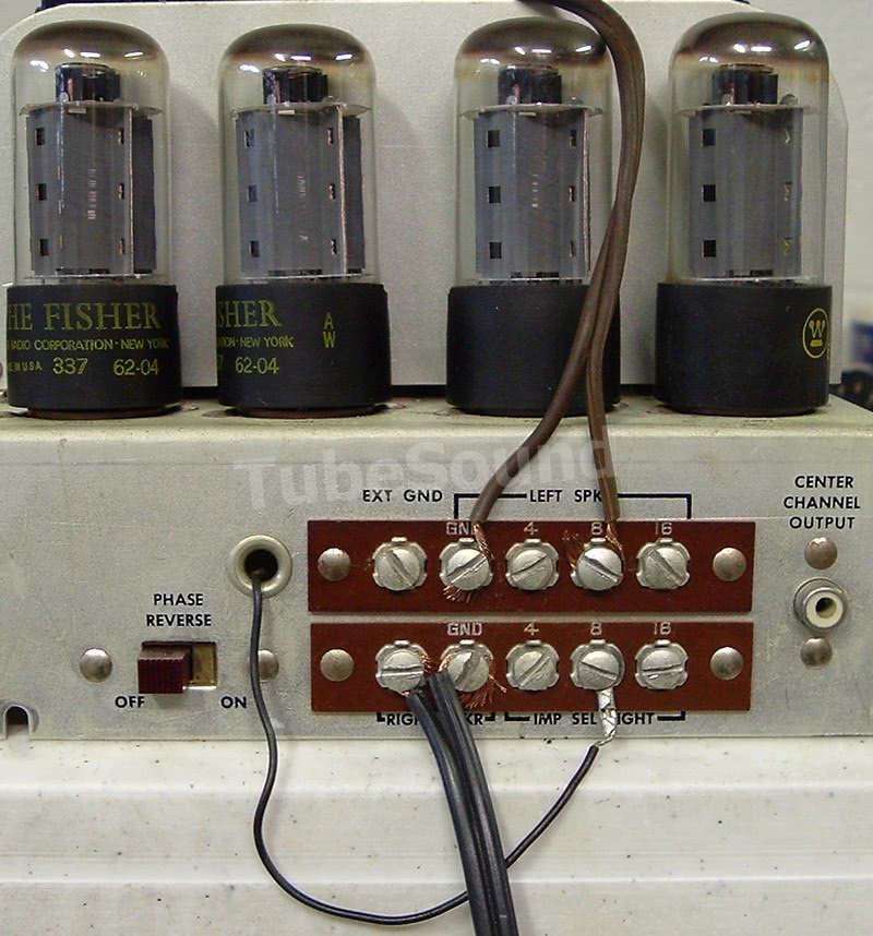
1) Q: “How do I connect speakers to my Fisher 500-B”?
A: This is confusing if you are not familiar with Fisher equipment. The photo below shows correct speaker connections to the 500-B. I have seen other 500-B models with a slightly different layout, but essentially one channel (here, the left speaker) is connected normally — between “C” and correct impedance. The other channel (here, right channel) is connected between its “C” screw and the unmarked screw next to it — exactly as the black lines painted on the receiver instruct. The only thing connected to this channel’s impedance screws is the impedance selector wire that runs through the chassis. The reason for this channel having a “different” connection is because of the speaker phase-reversal switch that you see alongside the speaker connection terminals.
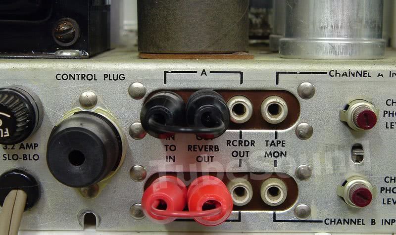
2) Q: “My Fisher has almost no output on either channel, from any input or FM tuner. The sound is coherent, but even at max volume it is extremely low and treble-sounding. Any ideas?”
A: You are probably missing the two reverb jumpers on the back panel that connect together the “Reverb In-Out” RCA jacks for each channel. It is not uncommon for these jumpers to be missing, and if so, you can make your own very easy. You only need to connect the “hot” terminal of the RCA jacks (the grounds are connected internally). The slight sound that you were hearing without the jumpers was a result of capacitive coupling.