
©2009, All rights reserved.
The article will discuss a cheap and easy way to test panel meters. The meter in your tube tester is an example of a panel meter. Occasionally you see flaky meter operation and suspect that the panel meter may be defective. Most techs know that it may not be safe to test a panel meter by placing an ohmmeter across its terminals — this attempt can ruin the panel meter (depending on the ohmmeter used) and will not reveal all of the panel meter specs anyway.
Most panel meters in vintage equipment (such as tube testers or capacitor testers) will be milliammeters or microammeters. The good news is that these panel meters can be tested, although extreme caution must be exercised. One mistake and you can easily ruin the meter, so “do not try this at home” until you have practiced with a large variety of junk meters and have sufficient experience and confidence in your skills. Even then, “triple check” everything before you proceed.

Many people think that you need to have expensive equipment to test panel meters. It would be nice to own a Simpson 2600 Laboratory-grade Calibrator (which cost $1,620 in 1965 and weighs 132-lbs). But you can make do with the following basic equipment: a variable power supply, a quality resistor decade box, a quality multimeter with mA and µA capability, and another quality digital multimeter that will accurately test millivolts. Likewise, you need an understanding of what you are trying to accomplish. Keep in mind that Ohm’s Law teaches that voltage, resistance, and current are all interrelated, therefore a panel meter that has its faceplate scale in “volts” CAN be tested as an ammeter.
In the following discussion, I will demonstrate testing a panel meter. You will (1) determine the full-scale spec of the meter (using the printed scale as your reference for full scale), (2) evaluate whether the meter action is smooth and accurate across its entire range, and (3) determine the internal resistance of the meter.
In this example, the makeshift gear that I have used is a small Sencore 24V DC variable power supply, a digital multimeter with both mA and μA ranges, a Hallicrafters HD-2 Resistor Decade box, and a digital multimeter set to autorange DC voltage.
I will begin by providing a brief summary of the procedure: the panel meter is disconnected from its circuit; the Variable Power Supply, digital ammeter, resistance decade box, and panel meter are all placed in series. A digital voltmeter will monitor the voltage drop across the meter and is therefore connected to the meter terminals (+ to +, – to -). By adjusting the power supply voltage and resistance via the resistor decade you will achieve a full-scale panel meter deflection. You will then read the digital ammeter to discover the full scale spec of the panel meter. Ohm’s Law will be used to determine the approx internal resistance of the meter. That is a brief explanation.
In more detail, start by disconnecting the panel meter from its circuit. Set your variable power supply(“VPS”) to Zero voltage output and leave it unplugged. Set your Resistor Decade to maximum resistance, and use a decade box that allows each resistor to be individually switched in series with the circuit (in other words, a resistor decade box with a rotary knob to select resistance is unsuitable for this task). Use your Multimeter to verify that you correctly set the high resistance in your resistor decade. Connect your equipment as follows:
- VPS (+) to your ammeter (+) terminal
- ammeter (-) terminal to panel meter (+) terminal
- panel meter (-) terminal to one post on your resistor decade box
- the other resistor decade post goes to VPS (-)
- Digital voltmeter (+) connects to panel meter (+), and voltmeter (-) to panel meter (-).
Triple check all of your settings and connections. Again, be advised that any mistakes can immediately ruin the panel meter, so you may get no second chances if you screw up.
With your VPS set to Zero volts, plug in your VPS and slowly raise the voltage. You will probably not see the panel meter needle move. I generally raise the VPS voltage to approx 5 or 6 volts, and if your panel meter has not moved, then I slowly decrease the resistance in the decade box.
As you decrease the resistance in the decade box, the panel meter will start to move up-scale. Use a combination of increasing VPS voltage and reducing decade box resistance to achieve a full scale reading on your panel meter. Read your digital ammeter and you have achieved your #1 goal of determining full scale spec of your meter. Write down that current number, and write down voltage across the meter. (Note that since you are using the printed scale on the meter faceplate, realize that the printed scale will not always indicate the complete full scale spec of the meter, which is sometimes slightly higher).
Use common sense — if your ammeter reads 1.04 mA, your panel meter is a 0 – 1 mA full range. You should understand that panel meters were designed with common-sense full range specs, such as 0-1 mA, 0 – 2 mA, 0 – 10 mA, 0 – 15 µA, etc. Strange results could indicate a defective meter movement or a problem with the needle sticking. Likewise, some meters have a shunt resistor inside the housing that may have changed value (common problem with Hickok meters). As a reference, quality panel meters were designed with a 2% accuracy (Simpson, Triplett, Weston, etc), and cheap panel meters (Shurite, etc) had a 5% accuracy.
Your second goal is to determine whether the meter has smooth action and is accurate across the entire scale. The meter action is easily checked at this point by turning down the VPS voltage and watching the panel meter needle action, then raising the voltage slowly until meter goes full scale. To check the accuracy at other points of the scale, simply check your results when the meter is reading half-scale, quarter-scale, etc. For example, at half-scale your ammeter should read 50% of the current at full scale, and the voltage drop across the meter should be half. Very easy. Write down as many test results as you desire. When you are done, turn down your VPS voltage to zero, then turn it off, and disconnect everything.
Your last goal is to determine the approximate internal resistance of the meter, which may be useful in troubleshooting. We can apply Ohm’s law to your test results to obtain a reasonable estimate of the meter’s internal resistance. Ohms Law instructs that Resistance = Voltage (V) / Current (A).
Example:
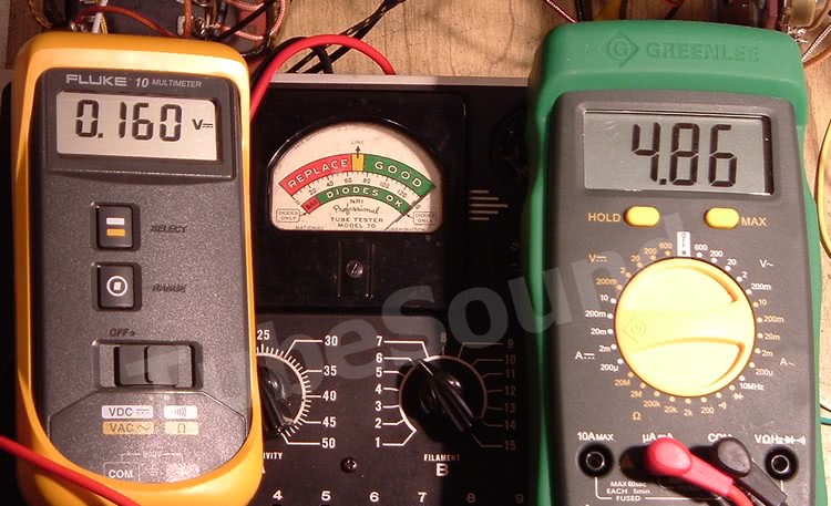
Testing a meter from an NRI Professional model 70 tube tester. Schematic reads “5 ma” and does not specify internal resistance.
Full scale tested: 0.160 V / 0.00486 = 32.922 ohms = 33 ohms
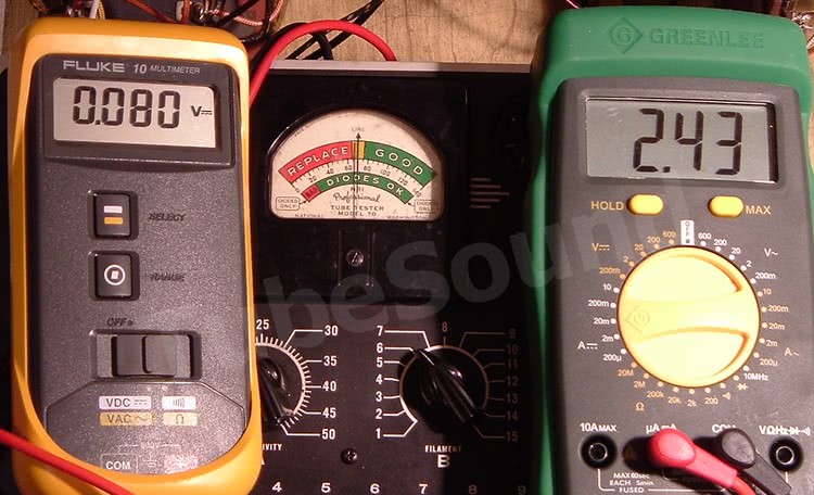
Half scale tested: 0.080 V / 0.00243 = 32.922 ohms = 33 ohms
Comparison to schematic (V = I*R): 5 mA * 33 ohms = 165 mV, which is an accurate result. (The meter will test 0.165 V slightly beyond the printed scale.)
In conclusion, this explains an easy low-cost way to test panel meters. With practice, this can be done safely and effectively. Do not practice on any meter that you cannot afford to ruin and proceed at your own risk.
Copyrighted, all rights reserved.
Ebay ID = rjputnak