
Most tube testers were not designed to evaluate balanced plate sections when testing a filament-type rectifier tube.
©2010, Bob Putnak, TubeSound.
When testing rectifiers such as 5U4, 5Y3, 5Z3 …have you ever wondered why one plate section tests stronger on your tube tester? Are all of your rectifier tubes really unbalanced?
I was recently sent an email asking for help to understand this topic. The answer is that most tube testers were not designed to offset the difference in potential between each plate section. For purposes of this discussion, assume that you are testing a rectifier tube with balanced plate sections.
BACKGROUND:
1. This discussion is only relevant to filament-type rectifier tubes. While most people use the words “filament” and “heater” interchangeably, they are not identical.
A filament is a directly-heated cathode; the filament is the cathode and emits the electrons. A heater is an indirectly heated cathode; it heats a separate cathode element. Common examples of filament-type rectifier tubes would be 5W4, 5Y3, 5U4, 5R4, 80, 83, etc. Examples of heater-type rectifiers would be 5AR4, 6CA4, 6X4, 6X5, etc. Therefore, a 5AR4 would not be relevant to this discussion. Most tube testers can evaluate balanced plate sections in a heater-type rectifier tube.
2. The purpose of the article is to explain to end-users the problems they will encounter when trying to analyze a filament-type rectifier tube for balanced plate sections using their tube tester.
Why would anyone want to do that? Historically, old-school technicians did not put much thought into needing a “balanced” rectifier tube. Similarly, I am not aware of any vintage tube tester manufacturer that instructed the user to test a rectifier tube for balanced sections and to reject those that were unbalanced. Nonetheless, some modern tube buyers have been told that they need to buy rectifier tubes with “balanced plate sections”.
DISCUSSION:
Most vintage tube testers were not designed to test for balanced plate sections. It was simply not considered important. As a result, most tube testers will test one plate section stronger than the other, leading the modern user to a false conclusion that the tube is unbalanced. In all cases that I am familiar with, the plate at the higher-numbered pin will always test higher, due to conventional filament wiring.
In most tube testers, each plate section is tested individually.[1] An AC voltage is applied to one plate and the resulting DC current is represented on the tube tester meter. The user then reconfigures the tube tester to test the other plate section.
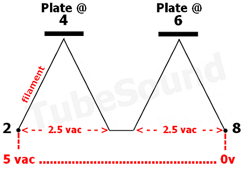
My graphic illustrates a common 5-volt filament type rectifier tube, such as a 5Y3 tube. The filament is a wire that has resistance. Notice that 2.5 volts are dropped across the filament area that supplies the electrons for each plate section.
The test discrepancy between plate sections is caused by two factors: (1) the plates are at different potentials, and (2) a low test voltage being applied to the plates.
Using RMS values, the plate at pin 4 has an average cathode voltage of 3.75 vac, whereas the plate at pin 6 has an average cathode voltage of 1.25 vac. With the filament and plate wired in phase, this cathode voltage subtracts from the plate supply voltage. (You could use Peak AC values, but since most people use RMS meters, I will stick with RMS values).
This subtraction can be easily verified. With a tube tester configured to test a 5Y3 (no tube in socket) and testing the plate at pin 4, measure between pins 4 and 8 while engaging the emission test. On most testers, this voltage will be 30 – 40 vac. Measure the voltage between pins 4 and 2, and you will find the entire filament voltage has been subtracted from the previous measurement. A similar effect is happening inside the tube, except that only a portion of the 5 vac filament voltage is subtracting from the plate voltage, and one plate section is affected to a much greater degree.
This test discrepancy between plate sections can be demonstrated in several ways:
1. If all you want to see is the test scores of the plate sections to be reversed (ie – the plate at pin 4 to test stronger, instead of weaker), just reverse the filament connections[2] and retest. This makes the plate at pin 6 the one with the higher average cathode voltage, and therefore lower test result.
2. For a more thorough discussion, I built a simple circuit to demonstrate this “effect” across multiple filament voltages. Dangerous voltages may exist. Do not try this at home. Furthermore, when experimenting in a tube tester, you need to reduce the meter sensitivity or else you will slam (possibly damage) the meter due to the higher efficiency of the solid-state diodes.

The circuit consists of two common diodes and four balanced resistors, all installed into an octal base. The sample circuit allows one to simulate the center of the filament for each plate section, and take measurements that normally would be impossible (since you cannot access the filament inside a working vacuum tube). The value of the resistors is not all that important to demonstrate the effect. We are only concerned with measuring the difference between plate sections. Measurements are taken across each diode. Since plate @ 4 has lower effective AC voltage, it follows that the DC output will be lower, thereby demonstrating why the plate 4 section tests “weaker”.
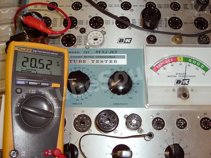
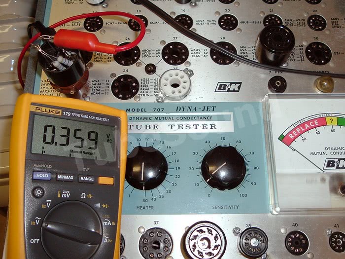
For this experiment, I used my B&K 707 tube tester. All measurements are RMS VAC. Plate supply voltage is approx 38 vac.
With 5 vac filament, plate 4 measures 19.13, plate 6 measures 20.52

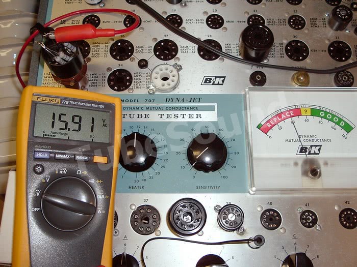
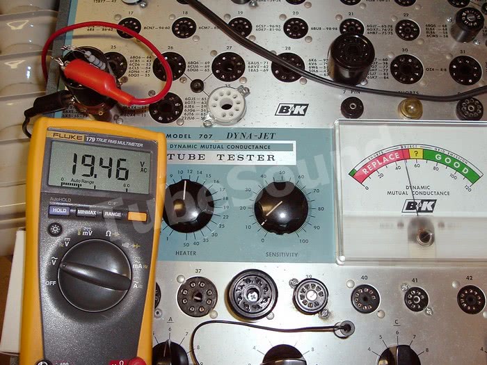
With 12 vac filament (a fictional “12Y3”), plate 4 measures 15.91, plate 6 measures 19.46
With 21 vac filament (a fictional “21Y3”), plate 4 measures 12.74, plate 6 measures 18.37


With 50 vac filament (a fictional “50Y3”), plate 4 measures 0.36, plate 6 measures 14.01. (The 50 vac experiment must be done quickly, because the resistors are under-wattage for this test).

Thus, from this experiment, you see that the filament voltage significantly changes the reading of the plate 4 section. In fact, at 50 vac filament, the average cathode voltage of plate 4 is so high that it swamps the entire plate supply voltage under these test parameters. This experiment demonstrates the effect of the filament voltage in relation to each plate section. In real life, only the 5 vac test is relevant to the rectifier tubes that you will be testing, so the numbers above demonstrate why the plate 6 section will always test stronger in a balanced rectifier tube.
If you understand the discussion above, you now realize that the low plate voltage test is really why you “see” the test discrepancy. In a real circuit, the plate supply would typically be 300 vac or higher, and the potential difference between plate sections would vary the operating voltage by less than 1%, an insignificant amount. But since most tube testers use a very low plate voltage to test rectifiers (30v – 50v), this difference in potential will cause a large test difference between plate sections.
Hickok apparently understood this subject, although I am not aware that this issue was mentioned in any of their documentation. Hickok does not test each plate section of a filament-type rectifier tube with identical test parameters. If you examine the Hickok setup chart, you will find that the higher-numbered plate section has a higher English/Shunt dial setting, and the higher English/Shunt setting slightly lowers the meter reading to compensate for the potential difference that I explained. The same effect is happening — the only difference is that the higher shunt/english dial setting for plate 6 is masking the test difference that you see on the meter.
So, if you always wondered why a Hickok uses different English/Shunt settings for each section of a filament-type rectifier tube, now you know. As a comparison, notice that the Hickok Shunt setting for each plate of a 5AR4 is identical, because a 5AR4 has a heater not a filament. Before you sing the praises of the Hickok configuration, understand that the rectifier test voltage is only approx 40 vac, which is quite low when compared to a real power supply circuit.
There are other tube testers that work much better to test for balanced plate sections in a rectifier. For example, the Jackson 648 series uses a high 225 vac test voltage, and the high test voltage makes the “potential” issue a non-issue, typically allowing balance to be checked with only a one percent margin of error. The 225 vac test voltage is also much more realistic when compared to a real power supply circuit.
CONCLUSIONS:
1. Most vintage tube testers will not test for balanced plate sections in a filament-type rectifier tube. The plate at pin 6 will always test stronger. This is normal behavior. There is nothing wrong with your tube tester, nor the tube.
The lower the plate voltage that your tube tester uses, the more exaggerated the unbalance will seem.
2. If having balanced plate sections in a filament-type rectifier tube is important to you, you can always work-around the issue by “knowing YOUR tube tester.” Make notes for what each plate section of a known balanced NOS rectifier tube will test on your machine. If you discover, for example, that your machine tests one section 10% stronger, then you have a reference to evaluate subsequent tubes of that same type. Very simple solution.
3. Ask yourself why the “old-school” technicians do not stress over whether their 5U4 has balanced plates. Before internet hype, this was never an issue.
regards,
Bob Putnak
Footnotes:
1 Some tube testers test both plate sections simultaneously. An example would be the B&K 500. Obviously, in this configuration, it is impossible to check the balance between sections. [Back to post]
2 Some tube testers make reversing the filament connections quite easy. Examples: “JS” on a Hickok can be reconfigured to “CY”; NRI 70 – swap the “D” setting with the “Fil Check” setting on the chart; Heathkit / Eico 625 / Knight 600 – move the #2 filament pin to the down position instead of #8. [Back to post]