
This article discusses repair and calibration of the Sprague model TO-3 Tel-Ohmike Resistor-Condenser Analyzer. Serious electrical voltages are present, repairs should only be attempted by a qualified technician. Copyrighted by Bob Putnak, all rights reserved.

Model TO-3 Tel-Ohmike “Capacitor Tester” is based on the older Sprague design.
It is a balanced-bridge design with the following specifications:
- Capacitance testing from 10 pf to 2000 uf, spread across 4 ranges
- Electrolytic Capacitance and Power Factor measured with polarizing voltage is applied
- Resistance testing from 2.5 ohms to 25 meg, spread across 3 ranges
- Capacitor Insulation Resistance test
- Capacitor leakage test using a true load from 0 to approx 660 V (factory design). Note that a good argument can be made to drop the overall polarizing voltage down to 500 vdc (as discussed below).
- Meter reads in DC Volts (up to 750), DC milliamps (up to 75 ma), or Megohms (up to 2.5 gigohms).

Repair and Calibration of Model TO-3
NEED PRECISION REFERENCE CAPACITORS? — For those of you doing your own Tel-Ohmike repair, I sell a set of 5 precision reference capacitors for $43 free ship USA. First, you get 2 precision reference caps (1 of 2.0 µf, 1 of 0.02 µf.) Your original 200-pf cap is left installed. Next, you get a complete set of 3 precision caps (1 of 2.0 µf, 1 of 0.02 µf, and 1 of 200-pf) for use in testing and calibrating your machine. This set is applicable to any Tel-Ohmike model, not just TO-3.


Need a remastered manual and updated schematic for Sprague TO-3 Telohmike?
$8 free ship USA.
The original schematic for TO-3 has several mistakes and ambiguities. Therefore, I have revised the schematic, corrected errors that I have found, and added notes to make the schematic more user-friendly. The schematic is available as part of my TO-3 paperwork package. To elaborate: I corrected significant drawing mistakes at switch 2F, added labels to define the functionality of range-standard resistors, added the trimmer pots to the bridge pot, added clarification to the installed values of several resistors, added a ‘Notes’ section for better overall understanding, and digitally cleaned-up the schematic with photoshop for excellent readability.
As always, start with the fundamentals. Thoroughly clean the unit and allow sufficient time to dry. There are two tubes inside 5Y3GT full wave rectifier and 6E5 magic eye tube. Test both tubes and replace as needed. Make sure that the meter is indexed at zero. (If it cannot be indexed at zero, open up the meter and check for mechanical problem). FYI – The meter is a 1 ma movement, 50 ohms resistance, 50 mV full scale. Add anti-parallel 1N4007 meter protection diodes across meter terminals. Clean all switches and potentiometers with Deoxit. As always, resistors must be checked for accuracy (paying special attention to range-standard resistors). Replace capacitors, paying special attention when replacing the range-standard capacitors (use good precision caps). For safety and protection, you may consider installing a 3-wire grounded line cord and 1-amp line fuse.
Power Supply
This model uses a traditional full-wave 5y3GT rectifier in the power supply, and with a standard rebuild and using a new 5Y3GT tube, the power supply outputs approx 660v. Mathematically, this means that the voltage-divider pot is dissipating 8.7 watts of power (660v over 50k resistance.)
Since originally writing this article, I have heard from a number of readers who are trying to restore a TO-3. The common question has been “Where can I find a replacement voltage pot? Mine is bad.”
SOLUTION! We have TOP QUALITY Ohmite replacement 50K Pot for your Sprague TO-3. Premium OHMITE brand, much higher 50W rating. $99.99 free ship USA, very limited supply.
Yes, the original 50K “15-watt” pot is prone to failure. This is certainly foreseeable due to the power dissipation — especially if the unit is going to be used for extended periods to reform electrolytic caps.
If you want to keep the original low-quality 15W pot and reduce the risk of burnout, I have modified the circuit to drop the polarizing voltage down to approx 500 vdc. This change reduces the power dissipation of the voltage pot to only 5-watts. The pot seems to run acceptable at this level.
In my opinion, this is a smart modification for any unit with the original 15w pot. Most high-voltage electrolytic caps have a working voltage of 450 vdc, 475 vdc, or 500 vdc. Thus, all electrolytic caps with working voltage of 500 vdc or less can still be leakage tested at 100% working voltage. While 600 vdc electrolytics do exist, they are seldom found in the field. Even if you had the need to test a 600 vdc electrolytic, you could still test it at 83.3% of its maximum working voltage (which is more than satisfactory to determine leakage.)
CAUTION – be aware that all exposed metal surfaces of the original voltage pot are “live” and are attached to the pot’s wiper arm. You will notice that the pot is insulated from the TO-3 chassis for this reason. This means that the voltage pot shaft is “live”, the pot mounting nut is “live”, etc — so do NOT work on the unit without a knob on the shaft that completely covers the shaft and pot mounting nut. Likewise, the setscrew that attaches the knob to the shaft is “live”, so make sure that the setscrew is sufficiently recessed into the knob far enough to prevent a shock hazard.
I modified the power supply in the following manner. The resistor values specified are guidelines. First, to minimize in-circuit modifications, I replace the 5y3 tube. Instead, I use a new octal socket to install a pair of 1N4007 diodes (anode of diode #1 to pin4, anode of diode #2 to pin6). Connect the cathodes together. I installed a high wattage dropping resistor (approx 6000 ohms, 10 watts) between the junction of the diode cathodes and pin 2 of the octal socket. (The TO-3 takes the DC power from pin 2 instead of pin 8). This drops the high voltage before the pot, and leaves the pot dropping approx 500 vdc.
Finally, you may need to adjust the plate voltage to the 6E5 eye tube so that it is within RCA operating parameters. By default and without any circuit modifications, the plate voltage on the eye tube far exceeds the 250V maximum that is specified by RCA, so even if you leave the full 600+ voltage on the voltage pot, you should still reduce the eye tube plate voltage to within RCA design specifications.
POWER SUPPLY NOTE: I have recently found an original TO-3 factory shipped with a 75k voltage pot, instead of the 50k pot. The 75k pot is of the same make and design as the 50k pot. This 75k pot was apparently a late production change, and it does run cooler because it only dissipates 5 watts of power. I saw no other circuit changes in this unit. If your unit has the 75k pot, you can probably leave the circuit at 600v without much risk of damaging your pot.
Calibration
Once the fundamentals have been done, you may continue with the calibration.
1. Calibrate Leakage DC Voltage.
These range standard resistors are located on the schematic at switch “R” of Meter Range Switch. Selector Switch is in Leakage position. If your meter movement and range resistors are accurate, no adjustments should be necessary.
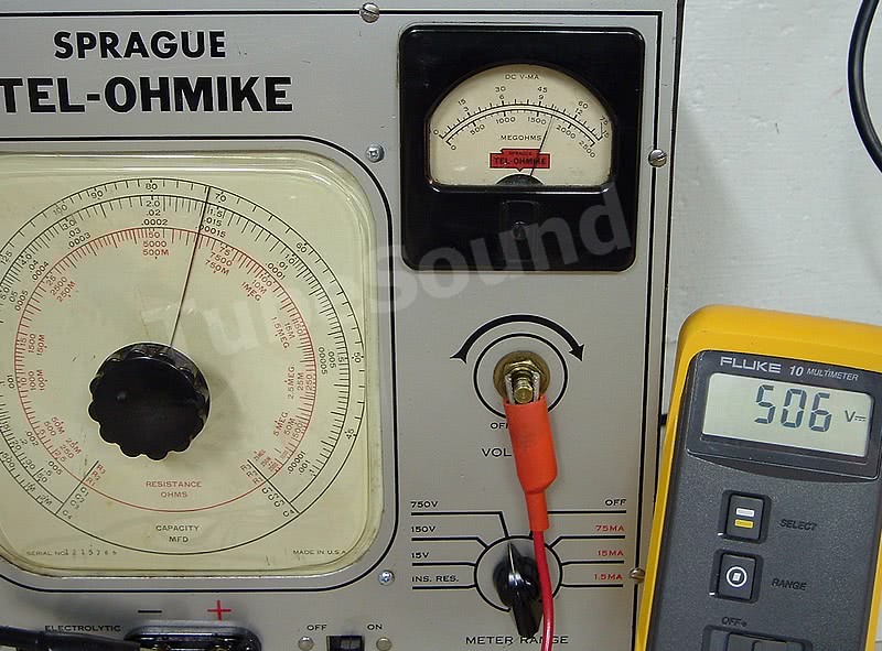
15V calibration: The 15V position uses a 15K range standard resistor in series with the 1 ma movement. Set the voltage pot at Off, meter range on 15v. Connect digital DC voltmeter to binding posts. Slowly turn up voltage and observe whether TO-3 analog meter reads same as digital meter. If not, tweak 15K resistor as necessary.

150V calibration: The 150V position uses a 150K range standard resistor in series with the 1 ma movement. Set the voltage pot at Off, meter range on 150v. Slowly turn up voltage and observe whether TO-3 analog meter reads same as digital meter. If not, tweak 150K resistor as necessary.

750V calibration: The 750V position uses a 750K range standard resistor in series with the 1 ma movement. Set the voltage pot at Off, meter range on 750v. Slowly turn up voltage and observe whether TO-3 analog meter reads same as digital meter. If not, tweak 750K resistor as necessary. Disconnect digital voltmeter.

2. Calibrate DC Current ranges
Connect a digital DC milliammeter in series with a variable resistance box and in series with the front binding posts. In addition to the TO-3 panel meter (which has internal resistance of 50 ohms), there are four fixed resistors that are in the circuit in all three current ranges. These resistors are the 90 ohms, 8 ohms, and 2 ohms at Meter Range Switch R, and also a 1000 ohm resistor at Selector Switch 2F. These three current ranges only differ in how the 90 ohm, 8 ohm, and 2 ohm resistors are switched into the circuit. If your meter movement and range resistors are accurate, no adjustments should be necessary. In fact, all these resistors must be accurate, because there is no way to tweak one of them without affecting all three current ranges.
I will now explain how each current range works using ohms’s law and assuming perfect resistance in all components. Of course, your meter movement resistance and range standard resistors will not be perfect, therefore slight deviations will be a fact.
75 ma calibration: The 75 ma range places 98 ohms resistance (range standard resistors of 90 ohm + 8 ohm) in series with the meter (which is 50 ohms), and also shunts this combined 148 ohms with a 2 ohm resistor and also a 1000 ohm resistor. Therefore, the combined parallel resistance is 1.969 ohms and can be measured with (-) prod of digital ohmmeter at panel meter (-) terminal and (+) prod of ohmmeter at the center terminal of the 50K voltage divider pot. At 75 ma for full scale, ohms law instructs a total of 147.675 mV. The meter sees 49.88 mV (approx 33.78% of the 147.675 mV) and the combined 98 ohms resistors see 97.79 mV (66.22% of 147.675 mV). Since the meter movement is 50 mV full scale, you can readily understand the circuit.


15ma calibration: The 15 ma range places 90 ohms resistance (range standard 90 ohm resistor) in series with the meter (which is 50 ohms), and also shunts this combined 140 ohms with 10 ohms resistance (range standard resistors of 8 ohm + 2 ohm) and also a 1000 ohm resistor. Therefore, the combined parallel resistance is 9.247 ohms and can be measured in the same manner as described above. At 15 ma for full scale, ohms law instructs a total of 138.705 mV. The meter sees 49.53 mV (approx 35.71% of the 138.705 mV) and 90 ohm range standard resistor sees 89.17 mV (64.29% of 138.705 mV).


1.5 ma calibration: The 1.5 ma range shunts the meter with 100 ohms (range standard resistors 90 ohm + 8 ohm + 2 ohm) and also shunts the meter with the 1000 ohm resistor. Therefore, the combined parallel resistance is 32.258 ohms. At 1.5 ma for full scale, ohms law instructs a total of 48.387 mV. The meter sees the entire 48.387 mV.


3. Insulation Resistance calibration
The relevant resistors in this circuit are the 10MEG-S range standard resistor at Selector Switch 3R; the 0.5 MEG-S range standard resistor at the Meter Range Switch R; and the 3000 ohm variable resistor mounted near the 5Y3GT tube. Assuming that you have verified accurate range-standard resistors, the calibration will be performed at the 3000 ohm variable resistor.
Set Voltage pot to Off and both switch positions to “INS. RES.” Connect a precision 1-gigohm resistor across the front binding terminals and turn the voltage control up until meter reads at 1000 Megohms. Adjust the 3000 ohm variable resistor until the magic eye tube indicator just barely starts to open (approx 1/64-inch opening) from a fully closed position. Vary the voltage up and down and recheck your accuracy. Since you are testing extremely high resistances on an analog piece of equipment, do not expect perfect repeatability. The goal is to be as accurate as possible. If desired, you may check the accuracy at other resistances, such as 500 megohm, 2-gigohm or 2.5 gigohm.


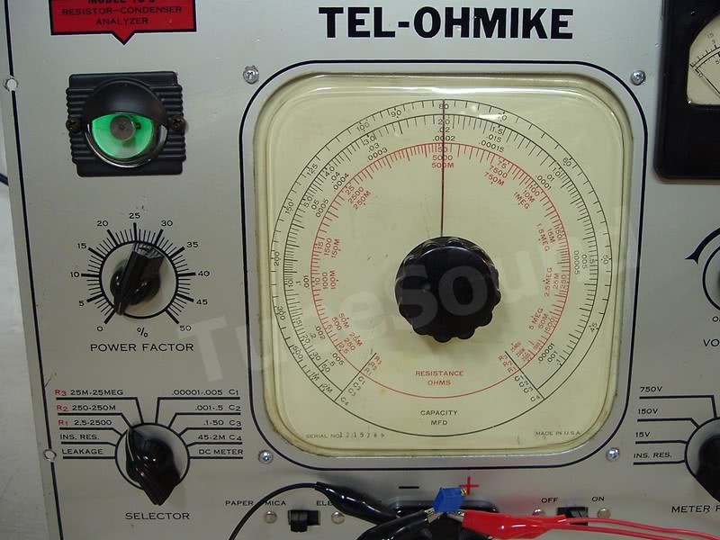
4. Capacitance Bridge Calibration
All balanced-bridge designs will be most accurate in the center of the dial. The relevant circuit components for this calibration are capacitors 0.02-S (0.02 uf), 0.0002-S (200 pf), and 2-S (2 uf) located at Selector Switch 2F, and range C4 is extended by the 0.15 MEG-S resistor located at Selector Switch 3R. All three capacitors must be good precision. The 150K resistor can be precision, or replaced with a 200K variable resistor and adjusted as necessary. For additional precision at the ends of the dial, install 100 ohm trimpots on both sides of the 7500 ohm bridge pot.
- Range C1 = model TO-3 has installed a Variable Capacitor adjusted to 200 pf
- Range C2 = 0.02 uf range standard
- Range C3 = 2 uf range standard
- Range C4 = 2 uf range standard extended by 0.15 MEG-S range expander resistor.
Assuming precision range-standard capacitors, ranges C2 and C3 are calibrated simultaneously — meaning that calibration of either of these three ranges will calibrate the other. When finding bridge balance with your precision test capacitors below, keep in mind that some capacitors require adjustment of the power factor knob.
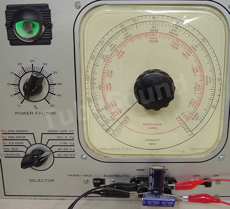
Calibrate the “Center” of the dial by connecting a precision 0.02 uf capacitor to the bridge, set Selector to range C2, turn dial until magic eye has maximum opening. Since model TO-3 has the needle soldered to the bridge pot shaft, you must loosen the pot from the faceplate and reposition the pot (and, therefore, the needle) at the “.02” dial position. Recheck accuracy and remove 0.02 cap from front posts.
Calibrate the “Left Side” of the dial by connecting a precision 0.5 uf capacitor to the front terminals. Check accuracy at the higher (left) side of the dial. Slight adjustments can be made by adjusting the 100 ohm trimpot that you installed. (The trimpot that connects to 3F selector switch). Disconnect cap from front binding posts.
Calibrate the “Right Side” of the dial by connecting a precision 1000 pf capacitor to the front terminals. Check accuracy at the lower (right) side of the dial. Slight adjustments can be made by adjusting the other 100 ohm trimpot that you installed. (The trimpot that connects to 3R selector switch). Disconnect cap from front binding posts.
Calibrate range C1 by connecting a precision 200 pf capacitor to the bridge, set Selector to range C1, turn dial to .0002 position. Use a screwdriver to adjust the 0.0002-S variable capacitor to 200 pf. Calibration is complete when magic eye has maximum opening. If range C1 is testing low on the lower side of the dial, you can connect a small 1 to 5 pf capacitor across the front binding posts. (Most people would not bother with a trivial deviation.)
Calibrate range C4 by connecting a precision 80 uf cap to the binding posts while using selector range C4. If bridge is not accurate, adjust range expander resistor “0.15 MEG-S” (located at 3R) until accurate.

Using a selection of precision capacitors, check your accuracy on each range C1 thru C4.


5. Resistance Bridge Calibration
All balanced-bridge designs will be most accurate in the center of the dial. The relevant circuit components are:
- Range R1 = 50-S range-standard resistor
- Range R2 = 5000-S range-standard resistor
- Range R3 = 0.5 MEG-S range-standard resistor.
Assuming those resistors are precision accurate, there is no further calibration that you can make without affecting the accuracy of the capacitance testing.
Calibration complete. Enjoy your rebuilt and calibrated Sprague TO-3 Tel-Ohmike.
Conclusion:
Sprague TO-3 Tel-Ohmike is very high quality capacitor tester, and certainly worthy of the “Tel-Ohmike” moniker.
Pros:
- Very high build quality. The unit is built-like-a-tank and uses a beefy transformer. No junk here.
- Traditional 5Y3GT Full-Wave rectifier power supply design makes for easy conversion to solid-state.
- Power Supply can supply 500 volts for true load Leakage testing of electrolytic capacitors.
- Controls have a nice layout with easy-to-read large print labels.
- Unlike newer Tel-ohmike models (such as TO-5), model TO-3 still has the resistance bridge functionality.
That said, model TO-3 does have some quirks/cons.
- Apparently the voltage pot is prone to failure if used to drop the full power supply voltage as was designed. To solve, you will have to modify the power supply to reduce the available polarizing voltage.
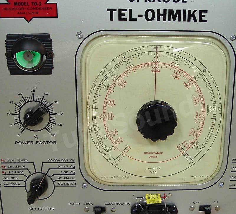
- Resistance markings on the faceplate use the letter “M” for ‘thousands’ and “MEG” for ‘millions’. For example, 500M is really 500,000 ohms (ie 500K). In this era, the “K” abbreviation was not universally used for ‘thousands’. Therefore, when making resistance bridge readings, you must remember to interpret “M” as “K”.
- Model TO-3 does NOT automatically discharge capacitors. This is a serious safety issue if you forget to turn down the voltage pot to zero before removing capacitor.
- The implementation of the voltage pot makes it easy to accidentally apply voltage when you should not; similarly, it is easy to slam the meter full scale when switching between meter ranges. You must think-before-you-act. Always check the voltage pot setting before-and-after all tests.
- The thin plastic dial cover is prone to warping, and therefore it is usually disfigured. A serious disfigurement will impede the dial needle/pot rotation, thereby forcing you to “be creative” in finding a way to make the dial work without impediment. Repairing this dial issue can add a lot of time to your project.
- The metal surfaces of the voltage pot are “live” and are insulated by a collar (from the chassis) and a plastic knob (from you).
regards,
Bob Putnak
eBay ID = rjputnak