
This article discusses repair and calibration of the B&K 600 / 606 tube testers. Both models can share the same tube setup data book, and therefore both models are functionally equivalent. Model 606 will be example shown in this article. Electrical voltages are present, repairs should only be attempted by a qualified technician. Copyrighted 2010 TubeSound, all rights reserved.
Cosmetically, these models look like a little brother to their larger siblings — B&K 700 and B&K 707. Model 600 shares the same color scheme with Model 700, and model 606 shares the same color scheme as model 707. The wood case construction is similar also.
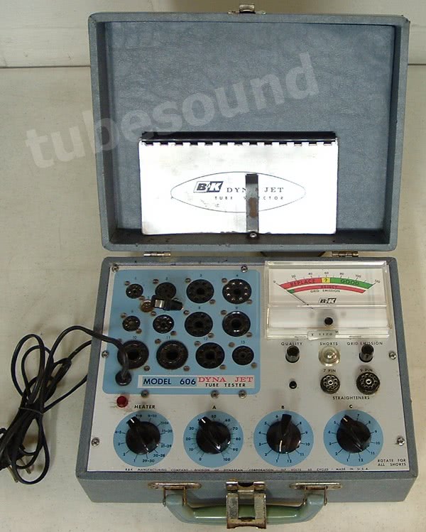


Electrically, models 600 and 606 are very similar (though not identical) to the “Switch” section (bottom panel) of the 700 / 707, employing the same grid leakage test and very similar tests for Emission Quality and Shorts.
Features/Specifications of models 600 and 606:
- Cathode emission test method
- Highly sensitive grid leakage test using 6BN8 vacuum tube circuitry (factory configured at 25-meg sensitivity)
- Adjustable Shorts test (factory configured at 1-meg sensitivity)
- Jet-Check sockets for fast and easy testing
- Two built-in pin straighteners for 7-pin miniature and 9-pin miniature tubes
- Test sockets available: 7-pin miniature, novar, octal, loctal, nuvistor, 9-pin miniature, 10-pin, 12-pin magnoval compactron duodecar, and decal.
- Dimensions (approx): 11 x 10 x 5 inches.
- Weight (approx): 6-lbs
- Internal tubes: one 6BN8 used in grid leakage circuit.


Need paperwork for your B&K 600 tube tester? I offer a remastered paperwork package for B&K 600 — operating instructions with large tube data setup chart, approx 60 pages total – $12 free ship USA.
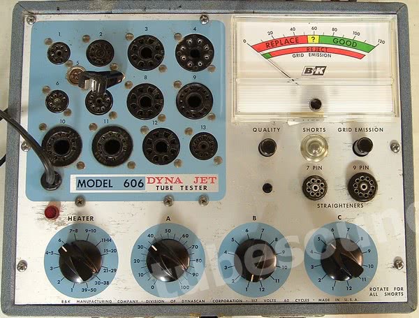
Machine Overview
- The panel meter is 1 ma dc full scale with resistance 100 ohms.
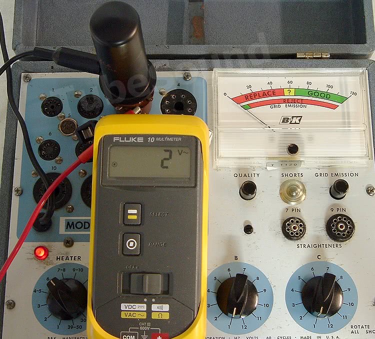
- Heater switch select the proper filament/heater voltage for the tube under test.
- Control A = Sensitivity control. Acts as a variable shunt across the meter to adjust meter sensitivity.
- Control B = Lockout switch. This switch will lockout (open/isolate) one pin. If no pin needs to be locked out, the chart indicates that position 6 is selected. Typical lockouts are (a) control grid has connection to 2 pins, the higher numbered pin gets locked-out; (b) tubes with additional heater tap, such as 35W4; (c) the Shell pin of metal envelope tubes (often pin 1, example 6L6 or 6SA7).
Example (c) explains why there is a small chart difference between configuring a 6L6 and a 7581. The original 6L6 has a metal envelope, and like most metal shell tubes, the shell is connected to pin 1. A #7581 tube is glass version of 6L6 and has nothing connected to pin 1.
Notice that if you were to configure the tester to pass through all pins (‘B’ switch at 6, such as for a 7581 tube), when you rotated Control ‘C’ to position #1 during the Shorts test, you would have 90 vac on the shell of the metal tube, thus creating a small shock hazard (low current, but you do not want the end-user getting a ‘tingle’ for any reason).

Hence, the chart configures the machine to isolate (lockout) the metal envelope.
Unfortunately, the pin to be locked-out with Control B does not follow standard RTMA numbering. The chart is as follows: Pos 1 = lockout pin 1. Pos 2 = lockout pin 2. Pos 3 = lockout pin 3. Pos 4 = lockout pin 4. Pos 5 = lockout pin 5. Pos 6 = no lockout, all pass through. Pos 7 = lockout pin 6. Pos 8 = lockout pin 7. Pos 9 = lockout pin 8. Pos 10 = lockout pin 9. Pos 11 = lockout pin 10. Pos 12 = no lockout, all pass through.
Control C = Grid Pin Selector. Selects the control grid for Emission Quality test and grid leakage test. For testing diode and rectifier tube sections, control ‘C’ selects the Plate pin. Control ‘C’ is also rotated to every position during Shorts testing.
REPAIR AND CALIBRATION
As always, start with the fundamentals. Check and replace all non-spec resistors. Check (or replace) all capacitors. The electrolytic capacitor should always be replaced. Polish and clean every socket pin. Treat all switches with Deoxit. Treat the calibration pots (for Shorts test and grid leakage test) with Deoxit. Treat the Sensitivity pot with Deoxit. (Failure to clean the calibration pots and Sensitivity pot is one of the most common source of inaccuracy in any tube tester.) Clean neon lamp bulb and socket. Check the 6BN8 tube (or replace with known good tube). Check secondary transformer voltages. If meter has suspicion of being defective, remove and test (full scale 1 mA dc, 100 ohms). Make sure that panel meter and Sensitivity pot are each mechanically indexed at zero.
SHORTS TEST

The Shorts test is started automatically when a tube is inserted into a testing socket. The Shorts Test places approx 90 VAC between the selected pin number at Switch C and all other elements. The user rotates switch C to all positions. The neon lamp will automatically light when a short (or internal connection) is detected.
Shorts Test Calibration: Set ‘B’ to position 6, ‘C’ to position 5. Use an octal test socket in Socket #3 and connect a 1-meg resistor between pins 5 and 8. Power on tester. Adjust Shorts Calibration control (R-6 on BK 606 schematic) so that neon lamp slightly lights. This sets the shorts test to 1-meg sensitivity, which is the factory default.

This Shorts test is not perfect because the tester does not have a full selection of lockout switches. When testing tubes that have multiple tube elements with multiple pin connections, actual shorts can be missed. Consider as an example tube 36KD6: control grid is connected to pins 5 & 9; screen grid is connected to pins 3 and 11; suppressor grid connected to pins 4 and 10.
The B&K chart settings are: B = 10, C = 5. The chart also notes “Normally shows short position 1-3-4-10.”
The first thing to notice is that Pin 9 is locked-out (Pos 10 locks out pin 9, as explained above), therefore there will be no false shorts to the control grid. That is good. But the chart also explains that regardless of what is going on at pins 1-3-4-10, the Shorts lamp will light. This can be a problem.

In this photo, pin 4 shows short with a perfectly good 36KD6 tube because pin 4 is internally connected to pin 10, and the chart explains that you can disregard this as correct behavior (which is correct in this example).

In this photo, I have connected a jumper wire between Pins 3 and 4, thereby shorting the Screen Grid and Suppressor Grid. While the Shorts lamp is still lit at Pin 4, the problem is that the chart tells you to disregard this short (because of the example in the left-side photo.) Therefore, since the tube tester behaves the same in both instances, you cannot know whether the tube has a short between those elements are not.
In summary, these B&K do not have 100% foolproof Shorts detection. They will not detect all shorts in tubes that have multiple elements connected to multiple pins, primarily suppressor grid shorts. The most common of these tubes are Ham-Radio style sweep compactron tubes, examples being 6KD6, 6GE5, 6HF5, etc. This is a minor limitation, and one that is shared with most tube testers regardless of brand or cost. If your tester does not have a full row of lockout switches such as found in a TC162 Mighty Mite or B&K 607, then you also have this Shorts test limitation.
CHART “FALSE SHORT” WARNING: Note that many 12-pin duodecar tubes manufactured by Sylvania connect pin 7 to the center of the heater/filament. Examples would be 36KD6, 49KD6, and others. The B&K chart does NOT warn of a “Short” at pin 7 on these tubes, even though the basing diagrams reserved Pin 7 for “IC” (internal connection). Therefore, many users throw away perfectly good duodecar tubes because they “find” a short at position 7, and since the chart does not tell you to disregard it, the user believe that it must be a tube defect. Wrong. Pin 7 is was normally not used for anything by most manufacturers, but Sylvania did use pin 7 internally for a center connection to the heater. If you examine the tube you will easily see that pins 1 and 12 connect to the ends of the heater, and pin 7 connects to the center of the heater. Therefore, it is a FALSE SHORT. I would guess that if I had a dollar for every duodecar tube erroneously discarded over the past 30+ years because of a “Pin 7 short” I might have quite a retirement fund by now! Again, this is why you have to know your tubes. Even the best tube test equipment will not tell you everything that you need to know. There is no substitute for experience.
GRID LEAKAGE TEST

The switch section Grid Leakage (also called ‘Grid Emission’) test puts the control grid negative to all other elements (which are all grounded). The tube under test has its normal plate to grid voltage applied, but the grid is biased beyond cutoff. If the tube has any grid emission or gas, positive voltage will build across the 5.6 meg resistor that is part of the 6BN8 grid circuit. This positive voltage removes the cutoff bias of the 6BN8 tube and causes the meter to deflect, thereby showing grid emission.

Grid Leakage Calibration: Tester should be allowed adequate warm-up time before leakage calibration is performed. Set ‘B’ to position 6, ‘C’ to position 5. Use an octal test socket in Socket #3 and connect a 20-meg resistor between pins 5 and 8. Adjust Grid Leakage Calibration control (R-3 on BK 606 schematic) so that panel meter reads “20” when Grid Emission button is depressed. This sets the grid leakage test 25-meg sensitivity, which is the factory default. The circuit can be calibrated more sensitive using a 100 meg resistor if desired, making it on par with a Mighty Mite. I prefer to use the factory sensitivity because the repeatability of the instrument is outstanding.
EMISSION QUALITY test
Emission Quality is not to be confused with “Grid Emission”. The emission quality test is a cathode emission test, where approx 60 VAC is connected between control grid and cathode. (For rectifiers and diodes, the test method places AC voltage between the plate and cathode.) This test evaluates the ability of the tube to rectify the AC voltage into DC.
The load resistance is 500 ohms (R-7 on BK 606 schematic), and can be quickly determined (tester powered off) by using a test socket in socket #3, ‘B’ switch at position 6, ‘C’ switch at 5, and measuring the resistance between pins 5 and 8 while pressing “Quality″ button. You will measure approx 500 – 600 ohms. This is not a precision check because you are testing through the entire circuit, but close enough to get an idea. The Sensitivity pot is a meter shunt and adjusts the meter sensitivity for each tube.
With a cleaned Sensitivity pot, proper indexing of pot and panel meter, and no other circuit defects, the Cathode emission test will not need any further calibration. Circuit note: notice that R-8 is a 47 ohm resistor that shunts the sensitivity pot. If you feel that your test results are artificially low or high, recheck R-8 and tweak as necessary. The schematic calls for 5% tolerance, or approx 45 to 50 ohms. A lower resistor value here will cause lower test scores, higher value will yield higher scores.
Conclusion
B&K models 600 and 606 are very nice tube testers. There is a lot to like about these. “Pros” — they are easy to use, lightweight and portable, and have good build quality. Once professionally serviced, there is little to go wrong afterward. These models do an excellent job at testing leakage, which is a much more important test than many users realize. The repeatability of test results is excellent. Finally, they test a large number of modern-style tubes.
No testers are perfect, so a few “cons” would be that obviously the tester has no “antique” sockets or chart configuration data to test the old “4-pin and similar” style tubes. The cathode emission test is not as advanced as other emission testers, but is certainly fine for the intended purpose. Shorts test is very good but not 100% foolproof (very few testers are…). There is no on-off switch — tester is turned on, and off, via power cord. (You could easily install a power switch if wanted.)
Overall, I like these models, primarily because of the build quality, leakage test, ease-of-use, and repeatability. A “solid” choice for anyone working with “newer” tubes, and a good compliment compliment to a Hickok or other “high-end” tester that really does not have the same excellent grid leakage detection.
regards,
Bob Putnak
eBay ID = rjputnak