This article explains stepper repair of a 1950’s Seeburg jukebox. High voltages are present. Repairs should only be attempted by a qualified technician. ©2010, Bob Putnak.
This article uses a stepper from a Seeburg C as the repair example, but the 160/200 play steppers found in late 50s and 60s Seeburgs are fundamentally the same concept.
The purpose of “the Stepper” (Step Switch & Relay Assembly) is to energize a selector coil and group solenoid in the jukebox pinbank according to the selection made on a 3W-1 Wall-O-Matic wallbox. A 3W-1 is a remote selector that was installed at each diner table to promote jukebox play.
Stepper repair is straightforward, although many problems can arise. The system is entirely electromechanical, and is based upon contacts opening and closing at proper times. This article will explain how I approach stepper repair.
1. You need a reliable working wallbox. Do not try to fix a stepper by using a wallbox of unknown condition. Don’t rely that someone told you that wallbox works. If you have not seen the wallbox working with a stepper and pinbank, then the condition is still unknown.
2. You need a reliable working pinbank. Do not try to fix a stepper by using an unreliable pinbank.
3. You need a quality repair kit, which will include the capacitors (of course, the 5µf cap will be present), plate load resistor, and service paperwork (schematic, parts list, Relay Adjustment chart, and complete Seeburg stepper theory of operation). My quality kit will include ALL of this.

New SEEBURG JUKEBOX WSR-5 WSR-7 Receiver Capacitor cap kit for B BL C G W R J JL — $24.99 free ship USA
Do not expect any repair kit to solve your problems — it is nothing more than a starting point. As you read below about the stepper that I repaired as the example for this article, you will understand that stepper repair entails much more than a “cap kit.”
4. You need a good 2050 tube. Make sure that the receiver has a good 2050 installed for the stepper. Often this tube is missing, because it is only needed for wallbox operation. In jukeboxes with a tormat selection receiver, the receiver should have two 2050 tubes installed — one for the tormat, one for the stepper. And just because your tube “lights up”, does not mean that it is good.

Tube #2050 (or equiv) for SEEBURG JUKEBOX, tested in an actual Seeburg jukebox and known good quality — $24.99 free ship USA
5. Check voltages at the 2050 socket. The selenium rectifier provides the DC bias supply for the 2050 tubes, and a transformer winding supplies plate voltage.
6. Inspect the stepper circuitry to see what previous servicing was performed, and look for obvious problems. You will often find an unsuccessful attempt to fix the stepper by installing a “cap kit.” You should also inspect the relay switch contacts for “readjustment” (ie bending). Also check the 47 ohm plate resistor for the 2050 tube. This resistor is often cracked — so often that I include a new 47 ohm resistor as part of my receiver rebuild kit.
If your receiver has the old cloth point-to-point wiring, carefully check each wire around the switch contacts for shorts. The old cloth insulation breaks down, and the leaf switches cut into the insulation. These shorts can be very time-consuming to find. Careful inspection at the beginning can save a lot of time later.
7. Check all coils for proper resistance using your ohmmeter. Each coil has stamped the resistance on it, for example — 500 ohms or 40 ohms. Your resistance test should confirm close readings. If you cannot get any reading across the coil, the coil is open and must be replaced. In rare instances, a coil may check good with ohmmeter but arc or short under load, and must still be replaced.
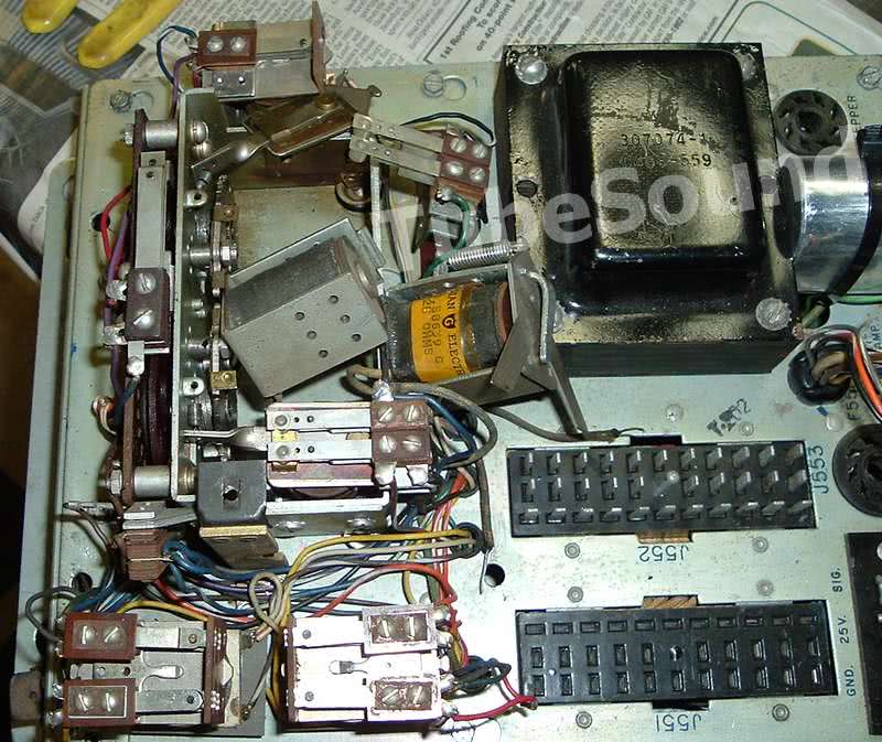
8. For a quality repair job, I suggest replacing all the capacitors, and checking all of the resistors. At a minimum, always replace the 5µf capacitor, the two electrolytic capacitors (300 mfd and 25 mfd), and the 0.05µf capacitor at the 2050 socket. As previous said, carefully check the 47 ohm plate resistor (may be 100 ohm in some units, can be replaced with 47 ohm). It is often cracked, and in the stepper that I repair below, it was totally missing! (Apparently it had cracked and someone just cut it out of the circuit.) Also, you will see a number of .05uf wax caps that are either mounted underside the chassis, or they criss-cross across the coil terminals (mounting location depends upon WSR model). These caps simply go across the three coils (TR#1, TR#2, Transfer Relay). Neatest installation will mount them directly across the coils instead of under the chassis or criss-crossing them up by the coils. (See next photo). The original mounting scheme was due to the physical larger size of the old wax capacitors.

9. Clean the Group Step Switch assembly (circuit board and pivot contacts) and the Unit Step Switch assembly (circuit board and pivot contacts).
10. Inspect the rubber grommets, replace if worn out.
11. Lubricate the pivot assembly for the Group Step Switch assembly and the Unit Step Switch assembly.
12. Meticulously clean all relay contacts, and verify continuity with your ohmmeter. Use the relay adjustment chart to verify proper spacing between contacts. (The adjustment chart is found on the stepper metal lid, but I also supply it with my Seeburg rebuild kit.) Inspect the fiber wafers that move the contact blades. Replace any that are cracked or defective.
13. The selenium bridge rectifier provides DC voltage to stepper relays. I do not replace the selenium rectifier unless necessary. If a replacement is needed, use a modern silicon bridge. I prefer to use one with very high amperage ratings, such as 25A. It looks better, cost is almost the same, and it should “last forever.” When installing a silicon bridge, it is smart practice to install a 1-Amp fuse in series with one leg of the transformer secondary (in other words, before the silicon bridge) to protect the transformer if the silicon bridge shorts.
14. To test the stepper, you only need a wallbox and a pinbank. (In fact, if you have enough experience, the pinbank is not even necessary.) No need to reinstall the receiver into the jukebox. Just connect the wallbox, and plug in the pinbank’s large black Jones plug. Power on receiver, let 2050 tube warm up, then make your selections at the wallbox. You will see the correct pinbank pin move outward if your repair has been successful. (Assuming properly working pinbank and wallbox).

That covers the fundamentals. Let’s examine a stepper that I repaired.
The receiver arrived nice and clean, and it was cosmetically very attractive. The stepper unit, though, had more problems than most. This made it a great candidate for this article.
Part of a “cap kit” had been installed sometime in the past, as an attempt to self-repair. The component leads were quite long, so I reinstalled those caps properly. The 5µf cap and 300µf cap had not been replaced, so I replaced those two caps.
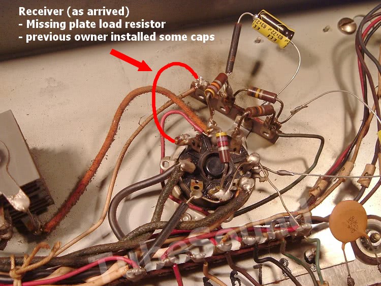
A quick glance around the 2050 tube reveals that the 47 ohm plate load resistor was completely missing, so the stepper had no chance of working without any plate voltage on the 2050 tube. This resistor is often cracked, so apparently it had cracked, and a previous owner cut it out of the circuit, leaving nothing attached to the 2050 plate socket pin. Closer inspection around the 2050 socket also revealed that there was a very bad solder joint at the 47k resistor. I installed the 47 ohm plate resistor and installed a new 47k resistor.

Next, I check each relay coil. The Transfer Relay was open. Luckily, Joe had a junk stepper laying around, and the Transfer Relay coil was transferred to his stepper. While this coil was good, it did have an issue. During testing, the coil did not release as quick as it should. I replaced the spring, and also used a trick that I learned a long time ago doing Laserjet repair. A small piece of electrical tape (sticky side towards armature) placed between the armature and coil helps it to release faster. (Also a great way to quiet a noisy relay). Subsequent testing of 200 selections (two complete passes of all 100), all perfect, proved proper timing of this relay.

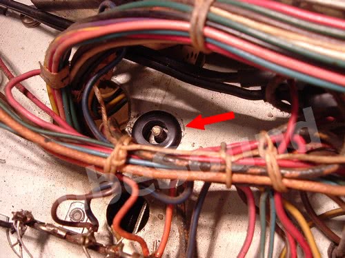
Next, I checked the insulating grommets. One of them was collapsed and dry-rotted. It was replaced with a modern black rubber grommet.
Next, I cleaned all of the relay contacts, and checked them for proper adjustment using the Relay Adjustment chart. After cleaning and adjustment, I manually check each contact make-and-break with my ohmmeter. You want excellent continuity (less than 0.5 ohms).
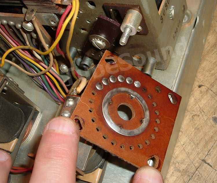
Remove and clean the Group Step Switch.
Three screws and one nut hold the Group Step Switch circuit board. As you see from the photos, these contacts are ALWAYS filthy. Some techs will not remove the board. They just spray some cleaner-lube and hope that is good enough. My opinion is that these contacts were never properly cleaned since they left the factory 50 to 60 years ago. They should be done properly.
Be sure to clean the two contacts on the pivoting wiper, and lubricate the pivoting wiper arm so that it is nice and free.

Remove, clean, and lubricate the Unit Step Switch.
Same process as above.
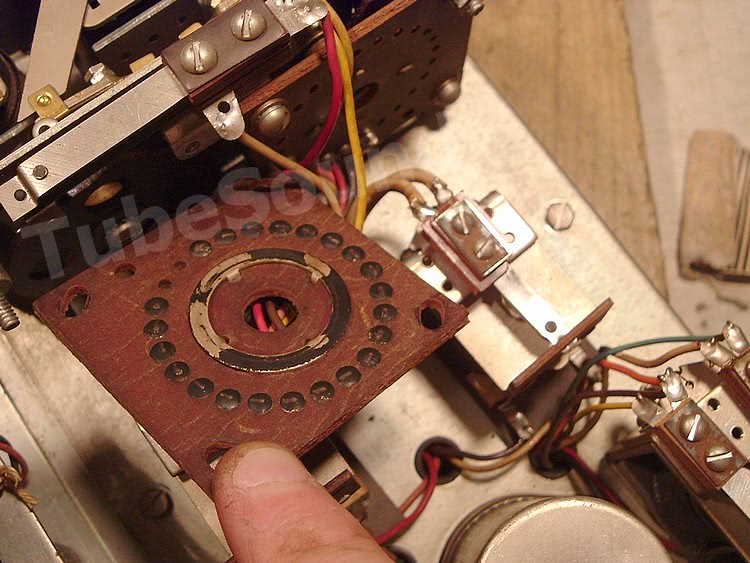

NOTE: During reassembly of the Step Switches, notice that the boards have room for adjustment. Manually ratchet up each step switch and eyeball the wiper contacts so that they are hitting the contacts squarely.
Finally, test the stepper. Again, the receiver does not need to be reinstalled into the jukebox. Connect a reliable wallbox and reliable pinbank (black Jones plug). The receiver can be plugged into an extension cord. Wait a minute for the 2050 to warm up, then make your wallbox selections. K10 requires the maximum number of pulses, so I start from K10 and work backwards.
In summary, the defects for this stepper were: (1) missing plate load resistor causing an open plate circuit, (2) bad solder joint 47k resistor, (3) open Transfer Relay coil, and then the replacement coil required tweaking, (4) collapsed grommet, (5) filthy Step Switch contacts, (6) maladjusted and dirty relay contacts, (7) defective 5µf and 300µf caps. I also “cleaned-up” the partial cap kit installation that was previously done.
That concludes the discussion. Steppers can have quirky problems that can be only be diagnosed “on the bench”, so please do not ask me to magically solve your problem via email. Without analyzing your receiver on the workbench, I cannot suggest anything that has not been discussed in this article.
regards,
Bob Putnak
TubeSound
