
This article will discuss repair and calibration of the NRI Professional model 70 tube tester. High voltages are present, repairs should only be attempted by a qualified technician. Copyrighted, all rights reserved.
Introduction
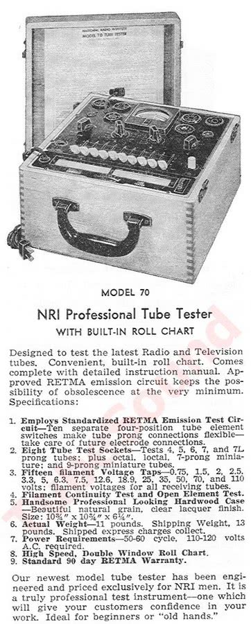
Built by Precision Apparatus Co for NRI, the high-quality craftsmanship of the NRI Professional model 70 tube tester is readily apparent. It has a beautiful hardwood case (appears to be oak or birch) with finger-joint construction.

Eight rubber feet protect your desktop in both the working position and the standup position. Internally, the tester uses a large beefy transformer and quality Pace (Precision Apparatus) meter movement. The tester has very small size, measuring only 10.75 x 10.75 x 6.25 inches (27cm x 27cm x 16cm) and weighs a hefty 10.4 lbs (4.7 kg). Most of the weight is due to the large transformer and hardwood case.
The NRI 70 has eight built-in sockets consisting of 4-pin, 5-pin, 6-pin, 7-pin large, 7-pin miniature, octal, loctal, and 9-pin miniature. All sockets use standard wiring (1-to-1, 2-to-2, etc.), and the control lever numbers correspond to their RTMA pin numbers (Lever 1 controls socket pin 1, Lever 2 control socket pin 2, etc.)
The makes operation much more simple than testers using non-standard socket wiring because each operating lever corresponds to its RTMA pin number (eg: moving lever 5 engages pin 5 for the tube). Standard RTMA wiring also allows you to easily make a Novar or Nuvistor socket adapter if so desired.
This unit has the latest known roll chart installed (1963), and I also include a new reprint of the manual (exclusive to TubeSound, because I personally recreated the instructions from scratch), and two large Supplementary tube charts. The charts have good coverage for many tube types: antique tubes (ex. 01A, PJ-8, #10, #27, #45, #50, #71A, #80, #83, 6E5/6G5, etc); Western Electric (ex. 274A, 300B, 350A, 350B, 401A, 407A, 408A, etc); Ham Radio (ex. 807, 809, 811A, 866A, 866Jr., 6146, etc), modern audiophile tubes (ex. KT66, 6CA7/EL34, 6550, 6CA4, 6BQ5/EL84, 5AR4, 7591, 7027, 6267,6336A, 6973, 7247, 7868, 7027, 6072, etc.) Obviously, with 10 function levers the tester is not designed to test modern 12-pin compactron tubes (such as 8950, 6KD6, etc.) although a small number of compactron/duodecar-base have chart listings and can be tested with adapters (6K11, for example).
The NRI Professional model 70 uses a traditional cathode emission test circuit to analyze tube quality. Shorts and Leakage detection is accomplished with a NE-57 neon lamp circuit. Sensitivity for leakage detection can be set by changing the value of R8 resistor to your preference.
Repair and Calibration

Need paperwork for your NRI 70 tube tester?
I offer a remastered paperwork package that consists of manual, schematic, and two tube data supplement charts (1959 & 1963),
all for $13.99 free ship USA.

Need a pair of new socket savers to protect your tube tester sockets?
Buy a pair of new manufacture socket savers: 1 each SS-8 (octal) and SS-9 (9-pin-miniature).
$29.99 free ship USA.
Loose meter glass seems to be a common issue on these.
Although a simple issue, it requires complete disassembly of the meter, carefully scraping off the old glue with a dental pick until perfectly smooth, checking the meter movement, cleaning the glass and meter face, reattaching the glass to the housing, and careful reassembly. During reinstallation, install a small electrolytic capacitor (approx 100mfd, 6v) across the meter terminals to smooth the meter action.

In preparation for the calibration, you always make sure that: the meter pointer is indexing at zero, check all resistors and potentiometers for accuracy and replace where necessary, replace the 0.1 mfd capacitor, clean all sockets/switches with Deoxit.

Remove sensitivity pot, open and clean with Deoxit, and reassemble. Be sure to treat the wiper, the slidewire, and the contact on the shaft. Check with ohmmeter for perfect continuity as you turn the shaft from one end to the other. When reinstalling, make sure that pot correctly indexes at zero. Finally, inspect all wiring (AC power cord, and also each wire connection at every tube socket pin).

LINE CALIBRATION
R2 is the line calibration control, and it has been “sealed” from the factory to prevent novice adjustment. You can free it up with WD40 and a dental pick, and then try to turn it gently with a flathead screwdriver.

Calibrate using the 235 vac high voltage secondary of the transformer. Turn the Line control until your meter reads 235 vac, then adjust R2 so that the meter needle indexes at 70-Line.

If you replace the old selenium rectifier with a new 1N4005 diode, either increase the value of R3 or replace the R2 “calibration control” with a variable resistor of higher resistance to allow additional adjustment due to the greater efficiency of the silicon diode.
Rotate the Filament switch to all positions and see that all filament positions are correct. Since the voltages are from individual transformer windings, each position will not be “perfect” but all should be very close.
Cathode Emission circuit
The NRI Professional uses a cathode emission test circuit. I have drawn a simple illustration to explain how this test circuit works. The diagram uses Load 4 as an example. First you will notice that all of the tube’s active elements (except cathode) are tied together and connected to the AC voltage through the load resistor, creating a diode. In this example, the tube’s plate, screen, and control grid are tied together and connected to the 235 v transformer secondary through a 2000 ohm load resistor. The cathode current flows through a voltage divider circuit. The panel meter is part of the voltage divider circuit and indicates the emission quality of tube. During testing, notice that the meter is shunted with approx 327 ohms resistance (comprising the full resistance of the 300 ohm sensitivity control + R1).

The NRI Professional uses a cathode emission test circuit. I have drawn a simple illustration to explain how this test circuit works. The diagram uses Load 4 as an example. First you will notice that all of the tube’s active elements (except cathode) are tied together and connected to the AC voltage through the load resistor, creating a diode. In this example, the tube’s plate, screen, and control grid are tied together and connected to the 235 v transformer secondary through a 2000 ohm load resistor. The cathode current flows through a voltage divider circuit. The panel meter is part of the voltage divider circuit and indicates the emission quality of tube. During testing, notice that the meter is shunted with approx 327 ohms resistance (comprising the full resistance of the 300 ohm sensitivity control + R1).
The NRI Professional provides four voltage/load combinations (Load Switch ‘C’) for the Emission test. The roll chart or supplement chart indicates the correct voltage/load that will be used for the test. The loads are:
- Load 1 = 35 v, 200 ohms (resistor R4)
- Load 2 = 35 v, 1000 ohms (resistor R5)
- Load 3 = 50 v, 5000 ohms (resistor R6)
- Load 4 = 235 v, 2000 ohms (resistor R7)
For best accuracy, the load resistors should be as precise as possible. If you checked all resistors for accuracy, cleaned the sensitivity pot, and set the Line calibration, your emission test results should be perfectly reasonable.
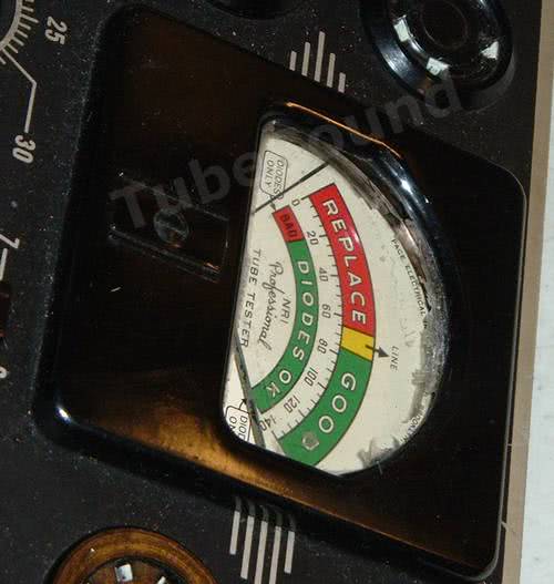
Now is a good time to observe that NRI uses different demarcation scores to separate the Bad-Questionable-Good ranges. Notice that NRI considers “75” to be the cutoff score between Questionable and Good. This number is a higher demarcation than other testers (ex. – Jackson uses 70 as a cutoff). Therefore, a tube testing slightly into the Green on some testers may fall into the Yellow range on the NRI. This is correct behavior and illustrates that different tube tester manufacturers had slightly different interpretations of where to draw the lines between good-questionable-bad. Hence, a “test score” is only relevant in context to the scale of that tube tester. (Even Hickok’s micromhos scores vary among different models). Tubes that check in the yellow range on the NRI will be useful for many projects.
Shorts testing
Using a test socket and jumper wire, you can check for proper Shorts detection. In this example, using the 4-pin test socket, pins 2 and 3 are jumped together. When individually moving Lever 2 or 3 up to the “F” position, the Neon lamp will lamp will glow brightly.

To perform a complete Shorts test, use a 9-pin test socket, and jumper from pins 1-to-2, then 1-to-3 (individually moving pins 1 or 3 up to F-position will show short), then 1-to-4, etc… working your way up to 1-to-9. Finally, jumper 1-to-Grid_Cap, and you will see a Short detected when moving levers 1 and 0 up to the F-position.
Leakage testing
The NRI 70 has factory leakage detection set at 620K ohms, and is controlled by R8. You can increase this resistor to 750K or 1Meg for more sensitive leakage detection if preferred. Checking for proper Leakage detection is accomplished in the same manner as the Shorts testing, except that instead of using a jumper wire between test socket pins, you will use a resistor to simulate internal tube element leakage. Notice that the Neon lamp glows more dim. (The more leakage — lower resistance — yields brighter glow).

MISCELLANEOUS NOTES:
Tube #7360 (Beam Deflection Modulator) is popular Yaesu FT-200/Tempo One transceivers. Tube #7360 can be tested on NRI Professional model 70 using these settings:
A = 24
B = 7
C = 2
D = 4 or 5 (not both…)
E = (none)
F = 2,3,6,7
These settings were created in collaboration with Dave W6NFU, who did extensive testing of several 7360 (both good and bad examples), and these settings were found to work well.
Final Thoughts:
The NRI 70 is an excellent choice for an “all-around” tube tester.
Pros:
- Manufactured by Precision Apparatus
- Outstanding craftsmanship — real hardwood case, finger-joint construction, quality meter and transformer.
- Good tube setup charts to satisfy most audio and antique radio needs.
- RTMA standard wiring makes it easy to identify which tube elements are shorted/leaky and also to create socket adapters if needed.
- Effective shorts test.
- Calibration procedure allows consistent results across units.
- Uses a Rheostat for Line adjustment to allow line accuracy.
- Line fuse
- Easy to use and maintain.
- Solid-state rectifier means that calibration will last longer than tube-rectifier testers.
- Small size requires little desktop space.
- The built-in roll chart works smoothly and quickly. Little things like this make a big difference in usability. Nothing is more frustrating than turning a slow-stiff roll chart for every tube that you want to test.
Cons (nothing major, just a few nitpicks):
- Each filament switch position is numbered sequentially (1 through 15) instead of being labeled with the actual Filament voltage. I would prefer the positions to read “2.5” instead of “4”, …”6.3″ instead of “7”, …and “12.6” instead of “9”, etc.
- You may want to slightly increase the sensitivity of the Leakage test (easily accomplished by changing R8).
- No compactron capability makes it not suitable to Ham Radio operators that use Compactron sweep tubes.
regards,
Bob Putnak.
eBay ID = rjputnak