
This article will discuss Mercury tube testers. The Mercury Electronics Corporation of Mineola NY produced a number of tube testers in the 1960s. All models are small, portable, and lightweight. Popular models include 990, 1000 / 2000, 1100, 1100A, 1100C, 1101. Models and comments will be added as I find time. Electrical voltages are present; repairs should only be attempted by a qualified technician.

Need a pair of new socket savers to protect your tube tester sockets?
Buy a pair of new manufacture socket savers: 1 each SS-8 (octal) and SS-9 (9-pin-miniature). $29.99 free ship USA.
Be advised that installation of socket savers in some Mercury models may prevent the case lid from closing. Buy at your own discretion.

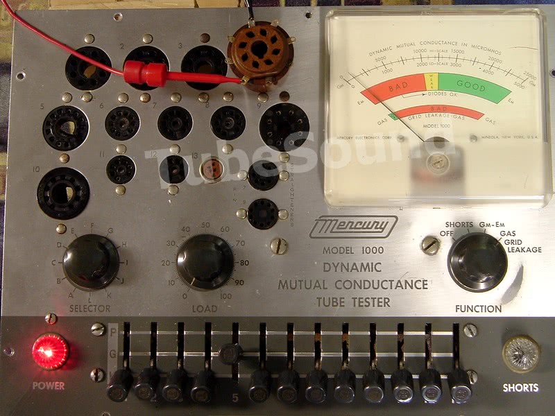
Mercury 1000 or 2000 Mutual Conductance
Model 1000 and 2000 are the same tube test circuit (model 2000 has a simple transistor test, not relevant to this discussion). I will use model 1000 as examples in the article.
Model 1000/2000 is a compact-size dynamic mutual conductance tube tester that has design elements similar other tube testers: à la Sencore Mighty Mite (jet-test sockets with heater pins preconfigured; socket panel is laid out like a Mighty Mite), from B&K (ALC circuitry), from Superior TV-12 (all amplifying tubes tested as a triode).
Need a remastered tube data setup chart for your Mercury 1000 mutual conductance tube tester?
$9.99 free ship USA.
As said, this model tests all amplifying tubes as triodes, with the plate and screen elements connected together for most tests.
The calibrated operating voltages (117vac line voltage) are measured with a DMM, from tube element to cathode:
- signal voltage = 1.0 vac
- high bias = -5.9 vdc
- low bias = -1.7 vdc
- plate/screen voltages = nominal 100 vdc pulsating, from cathodes of each diode of internal 6BJ8 tube for model 1000; model 2000 uses solid-state diodes. Since the circuit and setup charts are identical (except for socket numbering) for model 1000 and 2000, you can replace the diode sections of the 6BJ8 tube in model 1000 with 1N4007 diodes.
- ALC (automatic line control) = very similar to B&K, uses a pair of #44 bulbs to automatically adjust the Gm bridge, no user adjustment is available. No compensation is available for tube heater voltage variations due to line voltage conditions or transformer sag.
The bias voltage is set during testing by lever #11, with K position low bias (-1.7) and G position high bias (-5.9).
Repair & Calibration suggestions
The original carbon composition resistors will need to be replaced. The “metal-can” trim pots are often unstable and can be replaced with new modern wire-wound pots. Recap the entire unit. Clean all switches, bulb sockets, and Load potentiometer with deoxit. Make sure meter is mechanically zero-adjusted before starting calibration. Check the Load pot for zero indexing.
The factory calibration instructions can be found [here], but are only partially useful in my opinion. I would follow the “ZERO CAL” procedure and the “METER SENSITIVITY CAL” procedure. For the GAS/LEAKAGE calibration and Gm calibration, I take a different approach.
Shorts Calibration –
There is no adjustment in the tester itself; the machine has a preset sensitivity of slightly less than 1-meg. One suggestion is to replace the 820k resistor across the shorts neon lamp with a 2-meg pot, which will give you the ability to adjust the shorts sensitivity to a more sensitive level of 1 megohm to 2 megohm.
Grid Leakage Calibration –
My approach is to connect a 100-meg resistor between pins 5 & 8 of the 6L6 test socket, with lever 5 in the “G” position, and adjust R24 (1000 ohm pot) so that the needle reads right on the line between good/bad on the GAS scale.
Gm bridge Calibration –
At 117 vac line voltage, I set the operating voltages accurately (high bias at -5.9vdc, and signal voltage at 1.0 vac; check that the low bias is close to -1.7 vdc). I then check a series of tubes, primarily 6V6 and 6SN7, for acceptable test results. If the results are reasonable, which they generally are, no further adjustment is necessary. Note that a tube such as 12AX7 will test low since the operating parameters (100vdc plate, approx -1.7 vdc bias) are a poor operating point for this tube, and the Gm number on the setup chart should be taken with a grain of salt. In such a case, it is best to compare results vs testing a new tube of that type.
The emission test for most diodes/rectifiers (and a few power output tubes) uses a standard 25vac transformer winding with a 1000-ohm load resistor. There is a high-voltage (300vac) winding for testing rectifier tubes such as 0Z4, 1X2, or similar.
Schematic Mistakes
- The low bias voltage -1.7 vdc is printed on the wrong wire (the high heater wire) on the schematic for both models.
- Neither the schematic, nor the manual, explain that for the 12-pin compactron socket — pin #11 is controlled by lever #1.
General Opinion –
Pros:
- Easy to use.
- good grid leakage test.
- Small size.
- Tests compactrons & novars for Gm — albeit with a serious limitation in that it tests them as a triode, and in some instances, does not use the plate element at all.
Cons:
- All amplifying tubes are tested as a triode. Obviously, pentodes & beam-power tubes are not a triode, so this test method is a compromise.
- No lockout positions to open-circuit internally connected pins, thereby impossible to have a foolproof shorts test.
- The meter scale provides only ballpark Gm scores, especially on the high Gm scale.
- 12-pin compactron tubes, such as 6KD6, do not use the Plate element at all during testing. The plate is kept at cathode potential. These tubes are tested using the screen grid as the plate. The actual plate is only checked for shorts and does not play any role in the Gm test.
- Transformer sags on tubes with heavy heater current draw. For example, heater voltage measured directly on the heater pins of a 6KD6 tube (spec = 6.3 vac @ 2.85A) measures approx 5.2 vac (during all tests). This issue (transformer sag in a tube tester) is extremely common among tube testers.
- Obviously, the tester is not designed to test any antique tubes such as the old 4-pin dinosaurs. It tests only newer tube types from 7-pin-miniature through 12-pin compactron.
- The setup charts have a few bizarre quirks. For example, “6L6” entry has only an emission test. But, “5881” is tested for Gm and rated at 4000 micromhos, and “7581” is also tested for Gm and rated at 6000 micromhos. I don’t see any way to reconcile those 3 differences for essentially the same tube. Quite bizarre. This issue was never resolved in any Mercury tube chart that I have seen, from an old 1968 edition that I have, through newer 1976 printing.
- 12AX7 is tested at a poor operating point.


Mercury model 990 and 1100C
Models 990 and 1100C are electrically similar and differ mostly by cosmetic design.
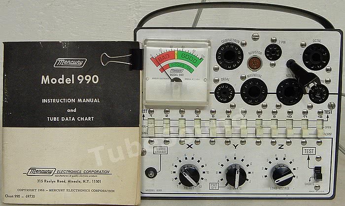

Model 990 will be the example photographed and discussed. These models are an example of a nice portable tube tester that packs a lot of punch into a very small package. It is Made in USA. Model 990 measures only 7.5 x 7 x 4 inches and weighing only 2.6-lbs, it is one of the smallest tube testers that you can buy. Model 1100C is also slightly bigger, and the size difference is because model 1100C has a wood case with lid. The portable size offers easy mobility for remote service calls. The instruction manual / tube setup chart is combined in one book, and neatly tucks away inside the unit. It has a carry handle for easy mobility.
Model 990 uses a traditional Cathode Emission test circuit with four selectable loads, and also checks for Leakage and Shorts. The leakage circuit is factory-set at 1-MΩ (this is the 1-MΩ resistor across the neon lamp), which means it will detect inter-element leakage from (solid short) up to 1 MΩ.

The 990 has eight test sockets: 12-pin Compactron, Nuvistor, 7-pin miniature, Octal, Decal, Magnoval, Novar, 9-pin miniature. This socket configuration is suited for people working on post-1950s tube equipment, including guitar amps, HAM radio rigs, 1950-1960’s jukeboxes, etc. Since the tester does not have the antique sockets (such as 4-pin, 5-pin, etc.), this model is not suitable for early antique radio servicing (1920’s to 1940’s).
Mercury 990 paperwork package: manual, schematic, and tube data setup chart, all for $13.99 free ship USA.
Mercury 1100C paperwork package: manual, schematic, and tube data setup chart, all for $13.99 free ship USA.
Servicing
Clean the unit, and inspect the line cord (replace if necessary.) Replace the 0.01 µF capacitor. The parts list shows a 100µF electrolytic capacitor, although it does not appear on the schematic. (This is the case with every Mercury emission tester.) This capacitor (100µF-6V) is not installed from the factory on every unit, and goes across the meter terminals (+ to +, – to -). Treat all switches and tube sockets with Deoxit. (This includes all rotary switches and all slide switches; work each switch vigorously after applying Deoxit. The top sides of the rotary switches can be polished by hand for even better cleaning.)

Use a multimeter to check continuity on both sides of the 12 slide switches: from Open-to-Test position, then Open-to-Norm position. Check continuity of all 12 circuit leads from each tube socket pin down to its corresponding slide switch. The top cap has continuity to slide switch 11. Check all resistors for values close to schematic. (R4 will be tweaked later).
Emission Calibration:
To begin, I must point out that some of the instruction manuals supplied with model 990 contained a schematic with errors. (For example, Chart 990 #69730). Load switch Z is drawn completely wrong on the bad schematics. If your schematic shows Z switch position #1 connecting to 10k resistor, then you have a bad schematic. Position #1 should have load resistor R4 ( 330Ω ), Position #2 (R5, 820 Ω), Position #3 (R6, 1500 Ω), Position #4 (R7, 10KΩ resistor in series with R6). The other side of this switch is drawn wrong also, but is not relevant to this discussion. The manual and tube data chart that I sell in my storefront has the correct schematic.
A quick glance through the Model 990 tube data chart will show that approx 95% of the tubes test with load #1. Therefore, Load #1 will be calibrated. The “Good” range of the primary scale on this tester goes from 50 to 100, and in this configuration a “standard” new tube will test approx 75. A new 6L6 tube will be used as a reference standard. If you do not have a “standard” 6L6 tube that you use for this purpose, you should acquire several new uniform 6L6/5881 tubes (same brand, same production lot). Adjust the value of R4 (the 330Ω resistor) until 6L6 tube tests at approx 75 — repeat the test with the remainder of the new 6L6 tubes. (The purpose of repeating the test with several factory uniform tubes is to make sure that you did not receive one tube that was “out of spec”. ) On the last Model 990 that I repaired, R4 value of 390Ω was optimal, but each unit should be checked individually.


The remaining three loads do not require tweaking because (1) the factory defaults are reasonable; (2) they are very seldom used (95%+ of the tubes use Load #1); and (3) some of these loads focus more on the lower (diode) good-bad scale and not the upper primary scale.
Model 1100C is easily calibrated by adjusting R8 meter shunt while testing a new 6L6 for test score in the 75 range.
Shorts and Leakage Calibration:
The 1-MΩ leakage sensitivity is standard. Check the value of R1, which is the 1-MΩ resistor across the neon lamp. This resistor should be 1-MΩ or slightly higher.
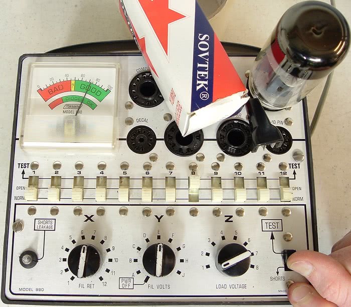
Leakage and Shorts can be checked by using a Test Socket, a pair of jumper wires, and a 1-MΩ resistor.

In the photo above, I am using an Octal test socket. A pair of jumper wires connect a 1-MΩ resistor between pins 3 and 6. You will see a moderate glow on the Leak lamp. If you use a resistor of lower resistance, the glow will be brighter.
Similarly, if you jumper those pins together (instead of connecting them thru a resistor), you can simulate an internal tube short as follows:

(Notice the brighter glow of the neon lamp when testing a Short vs. Leakage).
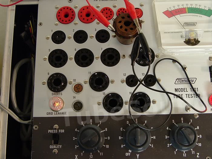
Mercury model 1101

Mercury model 1101 is another lightweight American-made portable tube tester from Mercury. The manual has a copyright date of 1967. Cosmetically, it resembles a Sencore Mighty Mite TC 154 in some ways – it has a large number of pre-configured sockets (16 of them), it has 3 control knobs at the bottom, the Shorts/Leakage test focuses on cathode-to-control grid and cathode-to-heater, and the 1101 is similar physical size (although lighter weight). It measures a small 12 x 9 x 4 inches and weighs only 4.1 lbs.

The 1101 tester that you see in these photos looks brand new. If not NOS, then it was seldom used.
One very nice feature – It has a complete set of five Pin Straighteners built into the unit, which allows easy pin straightening of all small-pin tubes (everything from nuvistor to compactron). It has a hard plastic case, a large easy-to-read meter, and metal carry handle for easy portability.

16 pre-configured sockets cover “all heater pin arrangements in use today” (as quoted from Mercury 1101 manual). Socket types include 7-pin, 9-pin, and 10-pin miniatures, Octal, Loctal, 5 & 7 pin nuvistor, Novar, 12-pin Compactron, Magnoval, and Decal. The unit also ships with a television picture tube test cable.
Mercury 1101 remastered paperwork package: manual, schematic, and tube data setup chart, all for $11.99 free ship USA
Electrically, Model 1101 uses the same test circuit as Model 990 (described in detail above), which is Dynamic Cathode Emission, Shorts Test, and Leakage Test. The neon lamp is sensitive to 2 MΩ, although the tester is factory set at the standard 1 MΩ leakage sensitivity. You could change R5 resistor for up to 2 MΩ sensitivity if desired.
Servicing
Use the same basic procedure as described for Model 990. Of course, the components are obviously designated differently. Here is a brief summary:
- For Emission calibration, the loads are found in Switch W, with Position ‘A’ (R6) being your primary focus, and calibrated using uniform 6L6 tubes.
- Switch X connects (in most tubes) the cathode to the meter for testing. In full-wave rectifiers, the plate is connected here.
- Switch Y sets the heater voltage.
- Switch Z connects (in most tubes) the Control Grid to the return circuit. In diodes (not to be confused with full-wave rectifiers), the Plate is connected here. Examples are 6H6 and 6Q7.
- The Shorts/Leakage test is automatic on this model. Once you setup controls X,Y,Z as indicated on the tube chart, and then insert your tube, the Shorts/Leakage test is automatically engaged. You do not need to engage any buttons/switches/knobs. If the Leakage lamp does not light after tube warmup, you do not have K-G1 or K-H leakage within the given sensitivity, and can proceed to the Emission test.
- Shorts Test functionality can be quickly checked for all pin positions: when Switches X and Z are in the same numbered positions (1-1, 2-2, etc…except for 12-12), the Shorts light should be bright, otherwise you have an open in the circuit. The exception is 12-12, which does not light.


Simulating (and testing) Tube Leakage and Tube Shorts:
Configure the tester to test a 6L6 tube, insert an octal test socket in Socket #4. Verify a bright Shorts light if you jumper together 2 & 8, …then 5&8, …then 7&8.
To check for proper Leakage detection, connect a 1-MΩ resistor between pins 2 & 8, …then 5&8, …then 7&8. At each of these three tests, the Leakage lamp should glow dimly. If it does not, reduce the value of R5 until the 1-MΩ leakage is detected.

Copyrighted, all rights reserved.
Ebay ID = rjputnak