
(©2008 Bob Putnak, all rights reserved.) This article discusses repair and calibration information for a number of vintage capacitor testers that all use the same fundamental test circuit. The article currently covers the EICO 950-series, PACO C-20, Knight KG-670, Heathkit C-2 and C-3, etc. (More models will be added on an ongoing basis as I find the time.) All of these models are almost identical in functionality and circuitry.

Set of 3 PRECISION REFERENCE CAPACITORS – for capacitor tester rebuild (Sprague Tel-Ohmike, Heathkit, Eico, Knight, Paco, etc…) – $33 free ship USA. You get the entire set of 3 reference caps (1 of 200 pf, 1 of 0.02 µf, and 1 of 2.00 µf). High precision, and the 200pf cap will be variable for maximum flexibility.

Set of 3 precision caps, plus extra ones for testing your calibration – $53 free ship USA
PLEASE SPECIFY YOUR MAKE AND MODEL OF CAP TESTER! Either tell me in the NOTES section of your payment, or email me that info. Thanks.
These units are known as a Resistance-Capacitance Bridge, an R/C tester, but are most commonly used as a capacitor tester. Extreme caution must be followed with any vintage capacitor tester because very high voltages are present during repair and while operating. They should only be used by knowledgeable technicians.


These models use a balanced bridge that measures capacitance from 10mmf up to 5000mf and resistance from 0.5 Ω up to 500-MΩ. During component value testing, the magic eye tube serves as the null-indicator. When the bridge is far from balanced, the target area of the magic eye tube glows completely closed green, and in fact overlaps. As the pointer dial approaches balance point, first the overlapping disappears and eventually the entire target area of the eye tube is completely open (dark). The bridge is balanced when the maximum dark area is indicated, and you can then read the value of your component on the faceplate scale.
Most models use the magic eye tube for both Leakage testing and component value testing. With the Eico 950A, leakage of Paper/Mica caps is indicated by the #1629 magic eye tube, but electrolytic leakage is indicated by the Neon bulb.
Any technician who repairs vintage tube equipment (such as tube amps, antique radios, vintage jukeboxes) will find that a quality capacitor tester is a useful test instrument.
Some common uses:
- Electrolytic capacitor testing. To properly test an electrolytic capacitor for leakage, you must apply its full rated working voltage. These units can supply up to 450V or 500V, depending upon model.
- Leakage testing of paper capacitors
- Testing very small capacitance values (as low as 10 picofarad).
- Testing very high resistance values (as high as 500-MΩ).
Repair and Calibration
General Notes for basic rebuilding:
Before investing any time and money, always check (1) the transformer and (2) the voltage divider pot (if applicable to your model). One or both of these parts are commonly defective, probably due to misuse from extended testing of shorted or leaky caps. The voltage divider pot is USUALLY defective. In my experience, having restored close to 100 units at this point in time, at least 70% of the units had a defective voltage divider pot.
Brand new higher-wattage Voltage Divider Pot – $44.99 free ship USA.
If you have a defective “voltage pot” in your Eico or PACO cap tester (value 100kΩ), then this is what you want. NOS NIB USA, higher wattage than original.
Next, test both tubes and replace as needed. Each R/C tester uses two tubes internally, a rectifier (6X4 or 6X5GT wired as a half-wave rectifier, or a #1626 triode wired as a half-wave rectifier) and a magic eye tube (6E5 or 1629). For model 950A, remove the Neon bulb, clean bulb connections and treat bulb socket with cleaner. Clean all switches and potentiometers. As always, resistors must be checked for accuracy (some resistor values will be changed for calibration, as I explain below). Replace all capacitors, and be sure to use precision reference capacitors in the balance bridge. Notice that the electrolytic capacitor that has its (+) end to ground must have a very high working voltage that exceeds 500V (which is higher than listed on the Heathkit schematic). Use two 22µf @450V electrolytics in series to replace this one capacitor. The other filter capacitor that has its (-) end to ground can be safely replaced with a 450V rated capacitor. For safety and protection, you may consider installing a 3-wire grounded line cord and 1-amp line fuse. If you install a grounded line cord, you can remove the AC line capacitor (C7 in schematic below) because it serves no purpose when a grounded line cord is installed. If you replace “C7” AC line capacitor, use a X1Y2 safety capacitor value .01uf.
The power supply circuit is similar in most of these cap testers.

Let us examine the Eico 950B schematic, which I have chosen because it conveniently shows the voltages on the schematic. You are dealing with 720 volts. This ~720 volts will be divided between the magic eye tube and the voltage-divider string. (For the Eico models, the voltage divider is P3 potentiometer; for models using fixed voltage switch positions, the voltage-divider string is the 25V/50V-150V-250V-350V-450V positions, comprising four 22k resistors and one 10K resistor. This 10k resistor should be 11k.) The Magic Eye tube sees all of the voltage that is not part of the voltage-divider string. When properly repaired, you will find (-520) volts B+, and the remaining 200V on the plate of the eye tube.
In this Eico schematic, R8 (the resistor going to ground across the electrolytic capacitor; this is resistor R3 on the Knight schematic) sets the current through the voltage-divider string.
For models with the potentiometer and 500V faceplate voltage (EICO 950 series, Paco C-20), this resistor must be tailored so the 5 mA current flows thru the string. 500V is dropped over 100,000 Ω (the value of P3 in the Eico schematic): 500V ÷ 100,000 Ω = 0.005 amp = 5 mA. Therefore, do not worry about the schematic value for this resistor — use whatever value sets the voltage divider string to 5 mA.
For models with the fixed-voltage switch positions (25/50V-150V-250V-350V-450V… Heathkit C-2 & C-3, Knight KG-670), this resistor must be tailored so that 4.5 mA current flows through the string. The current is easily calculated: each position in the voltage-divider string drops 100V, therefore 100V ÷ 22,000 Ω = 0.004545 amps. Therefore, do not worry about the schematic value for this resistor — you must use whatever value sets the voltage divider string to 4.545 mA.


EICO 950B and Paco C-20 Notes:
Since the faceplate on the Eico and Paco units show a maximum voltage of 500V, this power supply voltage (-520V, dropped by 20 volts to 500V on this Eico schematic with R7, a 3300 Ω resistor). According to the math, the exact resistor value would be 4000 Ω. (20V ÷ 0.005A = 4,000 Ω). This should allow accurate faceplate voltages (500V) on the Eico and Paco units. (If your Paco C-20 does not have this dropping resistor, you can add it for more accurate voltage readings.) Again, remember that the voltage divider string is set at 5 mA.
The 250k range expander resistor (discussed below) is used for both the highest capacitance range (50 µf – 5000 µf) and the highest resistance range (5 meg – 500 meg).
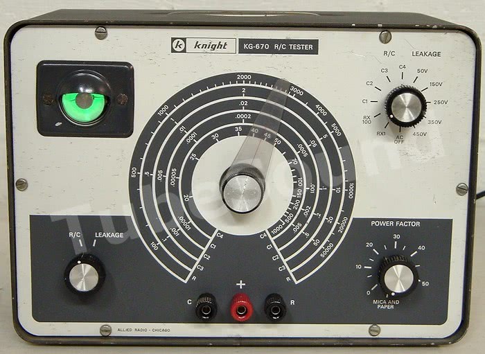
Knight KG-670 Special Notes:
Notice that unlike the Eico (which has a faceplate maximum voltage listed as 500V), the Knight faceplate represents that the maximum Leakage Test voltage is 450V. The problem is that the KG-670 does not have any dropping resistor in the circuit — only the voltage divider string. So, as it was designed at the factory, at least on several models that I have seen, the faceplate voltages will not be accurate on the Knight because the actual B+ voltages are much higher.

To correct this mistake, install a dropping resistor into the voltage-divider string. In two models that I rebuilt, a 15,400 Ω resistor (we need to drop the 520V to 450V, therefore need a 70V drop. Thus, 70V ÷ 0.004545 = 15,400 Ω) worked well (see photo for placement.) Similarly, the 10k resistor should be 11k for maximum accuracy. Now, the faceplate voltages will accurately represent the electrolytic leakage voltage range, and the magic eye tube has the proper voltage. Again, remember that the voltage divider string is set at 4.545 mA.
The 90k range expander resistor (discussed below) is only used for the highest capacitance range (20 µf – 1000 µf ).
Heathkit C-2 and C-3 Special Notes:
The power supply works the same way as described above — just set the voltage-divider string current to 4.545 mA as explained above. In fact, the power supply photos above were taken from a Heathkit C-3 unit. Note that the electrolytic capacitor that has its (+) end to ground must have a higher working voltage than listed on the Heathkit schematic. (Use two 22µf @450V electrolytics in series to replace this one capacitor.)
Turns out that Heathkit used different transformers in these models, and this change appears to be undocumented; one transformer puts out much higher voltage. (The lower voltage transformer, which is assumed by the Heathkit schematic, puts out approx 530 VAC. The higher voltage transformer, which is not factored into the schematic, puts out approx 585 VAC). If your transformer is the lower voltage version, then once you set the current in the voltage divider string you should be able to proceed without any additional dropping resistor. The voltage left on the eye tube should be reasonable.
If your transformer is the higher voltage one, then you cannot rely on the schematic. You will need to add a resistor in front of the voltage divider string to achieve accurate voltages on both the voltage-divider string and the eye tube, otherwise the plate voltage on your 1629 eye tube will exceed #1629 specs and therefore significantly shorten its lifespan. In several units I rebuilt that used this transformer, a 15.4k resistor placed into the voltage divider string worked well. So remember: if your tests reveal that your transformer is the higher-voltage one, you cannot rely on the voltages printed on the Heathkit schematic and must rebuild differently.

Also, notice that the lowest voltage switch position is printed “25V” on the faceplate. This is obviously wrong based upon the resistor values in the voltage-divider string on the schematic. (Heathkit repeated this mistake on both models.) You cannot reprint the faceplate, but you can make the faceplate voltages accurate. To correct this mistake, replace the 10k resistor in the voltage divider string with a 5.5k resistor, and the following 22k resistor with a 27.5k resistor. (Do not change any other 22k resistors.)

The 90k range expander resistor (discussed below) is only used for the highest capacitance range (20 µf – 1000 µf ).
NRI Professional model 311 Special Notes:
This model has 500V leakage test voltage, but uses a 250k voltage divider pot, yielding a 2mA leakage test current.
Factory Specs: capacitance test from 10pf to 1500µf, resistance test from 10 ohms to 150 megohms.
Setting the dial pointer:
Place a precision 2K resistor on the bridge, select the appropriate range, and turn the dial until the bridge is balanced. Once balanced, loosen the pointer setscrew, and reposition pointer onto the shaft at correct faceplate position.

More Precise Calibration
The above steps will achieve basic functionality of the instrument. The following notes will explain detailed calibration procedure, and which components affect each range switch position. You will need a dc milliammeter, a dc microammeter, a quality resistor substitution box (or equivalent), two different variable resistors, precision resistors and precision capacitors.
You need these precision resistors and precision capacitors to install into your R/C tester to create accurate ranges, and you also need precision resistors and precision capacitors to subsequently test the accuracy of your R/C unit. It is perfectly fine to use capacitors in parallel to achieve reference value, and resistors in series or parallel to achieve reference value.
Also, R/C checkers have maximum accuracy in the center of the dial for each test range. Test results are less accurate as you turn farther clockwise or counter-clockwise from center.
1. Each standard resistance range has one “reference” resistor of precision accuracy (1%) in the circuit. For the EICO models, the lowest range (20-Ω resistor), next range (2000-Ω resistor), next range (200-kΩ resistor). Each resistor must be precise. Some models do not have the range that uses the 20-Ω precision resistor.
2. An expanded resistance range (“5 Megohm to 500 Megohm”) is present on some models (Eico, for example). This range uses a reference resistor (200k) and also switches into the circuit an additional range “expander” resistor in series with the dial potentiometer to expand measurement range. (For example, R2 in the Eico 950B schematic.) This resistor is 250k or 90k, depending on R/C model. You can tweak this “expander” resistor for maximum faceplate accuracy, or install a variable resistor (trimmer) and adjust the value that achieves greatest accuracy with the faceplate. Note that this same expander resistor will also affect the highest capacitance range.
3. The lowest capacitance range uses a 200-mmf /200pf reference capacitor. This range tests for extremely small capacitance values. There are two calibration methods you can choose. First method is to install a mica/trimmer combination in place of the 200pf cap, then connect a precision 200 pf capacitor directly to the bridge terminal posts. Set the dial for 200pf and adjust the mica/trimmer combo for maximum eye opening. This method will factor in the distributed wiring capacity of the test instrument itself, although the ends of bridge will be a tiny bit less accurate (on this range only) because you are tweaking the value of the reference cap slightly off from 200pf. This is the same approach as using a calibration tube to “adjust” a tube tester by forcing it to read a “calibration tube” accurately. Here, you guarantee an accurate test at the center of the picofarad bridge range (…just as the calibration tube only guarantees an accurate test of the calibration tube itself, not necessarily all tubes…), but in exchange you compromise a little accuracy as you move farther from the center of the bridge.
A second method is to install a precision 200pf capacitor and tell the user to remember to subtract-off the distributed wiring capacity from your reading. This means that a 200pf cap on the binding posts will not balance at the 200pf dial position, but instead will balance above that dial position (maybe at 210, 220, whatever…). The factory used the 2nd method. Either method is reasonable. I prefer the first method as best approach for the typical end user who, in my experience, does not want to determine the distributed wiring capacity of his instrument and then remember to subtract it from the test result.
4. The second-lowest capacitance range uses a 0.02 µf reference capacitor. Best accuracy will be found by installing precision 0.02 µf capacitor.
5. The third capacitance range (typically the “0.1 µf to 50 µf ” range) uses a 2-µf reference capacitor. Best accuracy will be found by installing precision 2-µf capacitor.
6. The highest capacitance range uses a 2-µf reference capacitor and also switches into the circuit an additional resistor in series with the dial potentiometer to expand measurement range. (For example, R2 in the Eico 950B schematic, R5 on Knight schematic.) This “expander” resistor is 250k or 90k, depending on model. You can tweak this resistor for maximum faceplate accuracy, or install a variable resistor (trimmer). Note that this same resistor will affect the expanded resistance range (if present).
If the picofarad capacitance range tests low at the left side of the dial, you can solder a small picofarad capacitor of appropriate value across the +/- capacitor test terminals internally, thereby placing this small capacitance in parallel with the capacitor under test. This can create better accuracy at the low end of the picofarad dial (…but honestly, does anyone really need this degree of accuracy when testing picofarad capacitors?)


7. LEAKAGE Calibration (for models that use the magic eye to display all leakage results). As these checkers were shipped, no attempt at precision leakage calibration was made. The sensitivity rejects only very leaky capacitors. If you want a higher standard, use the following calibration procedure. Perform the electrolytic leakage calibration before the paper-mica calibration.
ELECTROLYTIC Leakage Calibration:
The electrolytic leakage calibration resistor is adjusted so that 2 mA of leakage causes the eye to “just close.” Therefore, any electrolytic capacitor with 2 mA of leakage (or more) will be a “reject.”
The electrolytic leakage calibration resistor ships as either 2,200 Ω (R11 on Eico 950B schematic) or 1,000 Ω (R11 on Knight schematic; and the only 1,000 Ω resistor going to ground in Heathkit). Replace this electrolytic leakage calibration resistor with a 5k variable resistor. It is easier to adjust this variable resistor outside the Checker, so temporarily connect it with jumper wires until the calibration procedure is complete, then connect it permanently.
Connect your DC milliammeter in series with a resistor substitution box (or potentiometer), across the capacitor test terminals. Set the Checker to test electrolytic leakage (be sure that the range switch is set for Electrolytic and not Paper/Mica). Choose the lowest voltage range for models with a switch, or approx 25V-50V for models with a potentiometer voltage adjustment. After the Checker has warmed up, engage the leakage test and adjust the resistor substitution box (or potentiometer) until your milliammeter reads 2 mA. Adjust the electrolytic leakage calibration resistor (the 5k variable resistor) until the eye is “just closed.” As you make this adjustment, the 2 mA will vary slightly, so you may have adjust both simultaneously. When complete, your milliammeter will show 2.0 DC mA and your eye tube “just closed.”

Note: the 2 mA maximum leakage sensitivity to pass/fail electrolytic capacitors is used by Heathkit in their factory calibration documentation for their expensive checkers. They are careful to point out that in some situations an electrolytic capacitor may pass more than 2 mA current and still be satisfactory. In practice, you will find that quality electrolytic capacitors will be well below this threshold, even large value electrolytics such as 100 mfd at 450V.
PAPER-MICA Leakage Calibration:
The paper-mica leakage calibration resistor is adjusted so that 2 µA of leakage causes the eye to “just close.” Therefore, any paper-mica capacitor with 2 µA of leakage (or more) will be a “reject.”
The paper-mica leakage calibration resistor ships as 470k (R12 on Eico 950B schematic; R10 on Knight schematic; the 470k resistor in series with the 1,000 Ω resistor going to ground in Heathkit). Replace this paper-mica leakage calibration resistor with a 5-MΩ variable resistor or equivalent. It is easier to adjust this variable resistor outside the Checker, so temporarily connect it with jumper wires until the calibration procedure is complete, then connect it permanently.
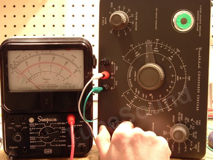
Connect your DC microammeter (such as a Simpson 260) in series with the resistor substitution box (or potentiometer), across the capacitor test terminals. Set the Checker to test paper-mica leakage (be sure that the range switch is set for Paper/Mica). Choose the lowest voltage range for models with a switch, or approx 25V-50V for models with a potentiometer voltage adjustment. After the Checker has warmed up, engage the leakage test and adjust the resistor substitution box (or potentiometer) until your microammeter reads 2 µA. Adjust the paper-mica leakage calibration resistor until the eye is “just closed.” When complete, your microammeter will show 2.0 DC µA and your eye tube “just closed.”
Note: the 2 µA maximum leakage sensitivity to pass/fail paper-mica capacitors is used by Heathkit in their factory calibration documentation for their expensive checkers. This calibration is MUCH more sensitive than these R/C units ship from the factory, and this will do a much better job at detecting leaky paper caps. Operational Note: the eye tube will open much “slower” during the paper-mica leakage test with this 2 µA sensitivity. The eye will be closed during capacitor charging and will not open until the capacitor has been fully charged. This may take a little time with larger paper caps. For example, a non-leaky 2-µf polyester film capacitor may take approx 20 seconds before the eye will open.
Examples of Operation
Note: Caution must be exercised when removing a capacitor from leakage testing. If your tester uses a potentiometer to control the voltage, slowly turn the voltage down to zero before removing the capacitor. If your tester uses a switch to engage the leakage test, you must switch it back to the R/C setting to allow the capacitor to discharge.
Example #1: I am testing a clean NOS American-made Mallory 40mfd @450V capacitor. Even after an extended period of time, the capacitor still shows leakage at voltages as low as 250V. (All electrolytics will show leakage at first, but will subside if they are not defective). After attempting reformulation, this capacitor is defective.

It is important to note that modern capacitor testers would have told you the capacitance value, and told you no shorts, thereby giving you a misleading test result of ‘good’. In fact, the capacitor has excess leakage starting at 250V, and is defective for its rated working voltage. You can now see the value of the vintage high-voltage capacitor tester.
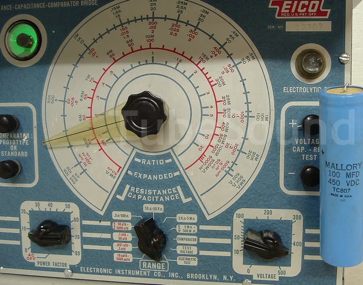
Example #2: No objectionable leakage in this NOS American-made Mallory 100-µf at 450V electrolytic capacitor, testing at full 450V voltage. You can feel confident that this capacitor will work excellent in circuit.
regards,
Bob Putnak, © 2008-2009.
eBay ID = rjputnak
A Note About Capacitor Reforming:
Capacitor reforming is the attempt to turn a currently defective cap into a properly working cap. This is attempted by slowing increasing the voltage applied to a capacitor over an extended period of time (to allow the chemical formula inside the capacitor to reformulate).
Capacitor reforming is a popular topic and has a variety of opinions about its effectiveness. Some techs strongly want to reform old caps if possible, usually to retain “originality” in the item they are repairing (often antique radios). Other techs never reform, believing that they cannot rely on a reformed cap for any extended period of time.
Reforming is a very time-consuming process, a “dark-art” to a certain degree, and results are very sporadic. Many caps are defective and cannot be reformed. Some caps can be reformed if enough patience is employed. Is it worth your time and effort when failure may be inevitable? In my opinion, if you are evaluating a stash of NOS high-voltage electrolytic (especially Can-style), then it is probably worthwhile because (1) most should reform rather quickly, (2) the likelihood of success is high, (3) the cost of new exact replacement is often expensive. However, reforming used capacitors is much more questionable endeavor, and the time expended to reform will often be more expensive (assuming that you value your time) than the cost of a new replacement.
Please note that trying to reform “bad” caps can damage your cap tester, specifically the transformer and/or the voltage divider pot. These cap testers are NOT the device to use to try to reform caps. And if you lack the experience to determine which caps have a likelihood of success, and which ones should not be attempted, then I would suggest that you forget about reforming.
For most people, I would suggest using a cap tester in the same manner that you would use any other piece of test equipment — to spot defects and replace the defective component. It is highly useful in this regard.