This article explains the circuit changes that Jackson made when they eliminated the 1S5 tube in favor of a solid-state diode for the Line. The changes below are those made by Jackson, and will allow you to convert your early 648 model to solid-state using the same method that Jackson used in their newer 648 models.
My Jackson 648 restoration and calibration article has been updated with a much easier solid-state conversion method (that works perfectly, also!) The discussion below is useful for those people who are curious about the method that Jackson used, or those people who wish to implement the same method (even though it takes more effort).
—
Newer versions of the “648” (648R, 648S, etc…) use a solid-state circuit instead of a 1S5 tube. The 1S5 tube is found in the earliest models, “648” and “648A”. As previously explained, the 1S5 tube is very important — it’s sole function is to monitor the line voltage and allow you to properly ‘set the Line’.
The following discussion will show how to eliminate the 1S5 tube and upgrade to the solid-state circuit found in the newer models. This project is not for amateurs, will require work, and will require recalibration of the Line Control. The benefit is that the tester calibration should remain accurate much longer with the solid-state circuit. Plate Current accuracy is not affected, except to say that accurate plate current scores require accurate Line calibration. Thus, upgrading to a solid-state Line control will benefit accuracy and repeatability.
Parts needed: 5000-ohm variable resistor, 1N4007 diode, piece of wire (the 648S uses a green coated wire, if you want to be consistent), and a copy of the 648A and 648S schematic.
In summary, the newer models replace the 1S5 tube with a diode, change R15 variable resistor value to 5000 ohms, and have wiring changes in the “X” and “Y” button switch banks. This method copies the changes that Jackson made in their newer 648 models. (It is certainly not the only method, nor the easiest.)
To begin, remove the 1S5 tube and the original 400-ohm variable resistor (R15) from the terminal strip. Leave the terminal strip in place. A white-wire-with-black-trace is attached to the center terminal of this resistor, and this wire goes to the 1S5 tube socket. Cut this wire at the tube socket, and remove old R15 and this white/black wire.
(Removing old R15)
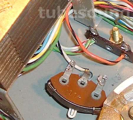
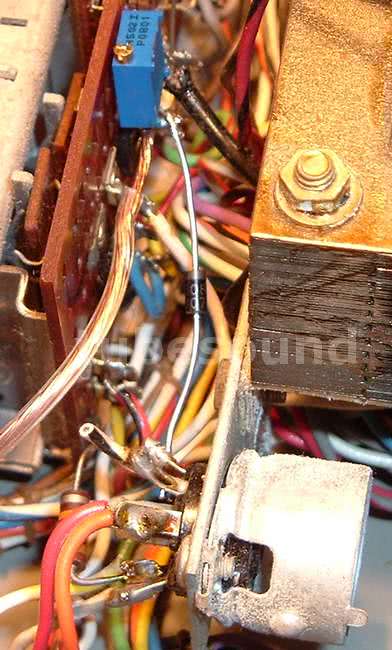
Take the new 5000 ohm variable resistor and solder the banded side of 1N4007 diode to the center terminal. Observe on the schematic that the one end of R15 is attached to the (-) from the transformers. If you follow this circuit, you will see that it also connects at Pushbutton “C” on the upper “WVU” pushbutton bank. In fact, the black (-) from the transformer actually is connected here. Therefore, this Pushbutton C junction will be a very convenient location to install the new (R15) 5000-ohm variable resistor. Solder one end of this variable resistor here.
(Good location to install new R15 and Diode)
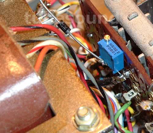
The other end of the diode connects to pin 4 of the tube socket (R16 resistor is also connected to pin 4).
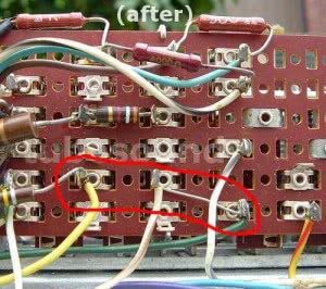
Run a wire from the remaining end of the 5K variable resistor to the 30V transformer lead (white-wire-with-brown-trace), which is found in the pushbutton “X” bank, the terminal below the white-wire-with-gray-trace. (The Jackson 648S uses a green color wire.) Examine the “after” photo below to see where this Green wire is attached on model 648S; it is on the bottom right side the photo, inside the red-circled area.
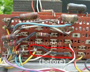
At this point, you need to study these two photos to show how the wiring must be changed. I will describe the changes to the best of my ability, but examine the photos and schematics. I have circled in red the changes that must be made. The photo on the left is “before” — what your 648/648A looks like now. The second photo is “after” — from a model 648S, which has the updated wiring for the solid-state circuit, and what you must achieve. Click each photo to enlarge.
I would describe the change as follows: on the same terminal where you just connected the “green” wire that you ran from the new 5K variable resistor, there is a short jumper wire with black heatshrink going to the junction of R14 resistor and a solid yellow wire. Remove the black jumper wire from the terminal where it meets the yellow wire and R14. Move this end of the black jumper wire one step to the right, to connect to the white wire with brown trace.
That concludes the Jackson solid-state circuit conversion, and now Line recalibration must be performed.
regards,
Bob Putnak.
eBay ID = rjputnak

