
This article will discuss repair and calibration of the Jackson 648-series tube tester. It will also discuss the procedure to eliminate the 1S5 tube from models 648 and 648A. High voltages are present, repairs should only be attempted by a qualified technician. Copyrighted, all rights reserved.
Introduction
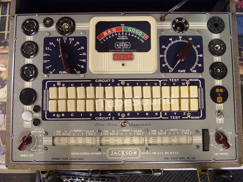
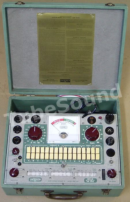
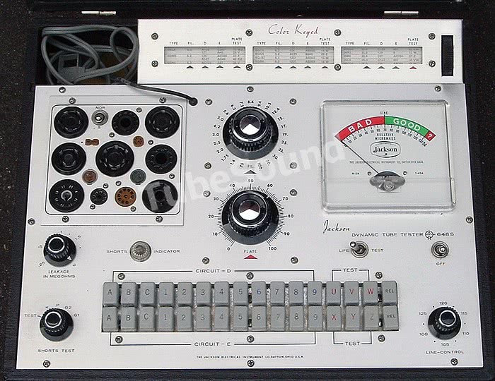
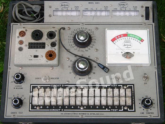
The Jackson 648 was available in several versions, including 648, 648A, 648P, 648R, 648S, 648-1, 648-1T. The basic circuitry is fundamentally the same in all versions, with only minor changes (socket layout/configuration, adjustable grid leakage circuit in 648-1T).


I am a big fan of the Jackson 648. It is definitely one of my favorite tube testers. While it does not employ a mutual conductance test circuit, it does use an advanced emission circuit that applies separate element voltages to each tube element, and separate load circuits are also used. “These voltages and loads have been carefully selected for each tube to meet most ideally the normal operating condition of the tube.” (Source: 1950 Jackson catalog).
In my experience, the Jackson circuitry is very effective, and often will surprise you with accuracy that approaches Hickok’s coveted “mutual conductance” test method.
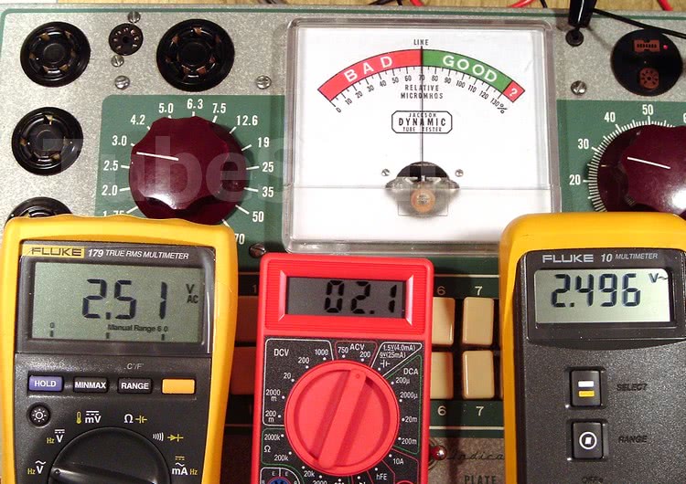
Example: testing a weak 6N6-MG (metal envelope) triode tube:
(as tested with calibrated Jackson 648A)

Here is another comparison:

(Jackson 648A testing a very weak triode section in a Mullard 12AX7)

(Calibrated Hickok 6000 testing the same triode section of the Mullard 12AX7, using the Hickok good-bad scale.)
As you see from the above examples, the Jackson 648 is a very effective tube tester.
Another great feature of the Jackson 648 series is the huge amount of tubes that can be tested.
With a modern chart, and possibly the addition of some sockets/adapters (depending upon your version of the 648), you can test just about every tube — everything from an early 01-A triode, to a Western Electric 300B, to a modern M2057 compactron.
This flexibility cannot be overemphasized, as many people do not want to own multiple tube testers.
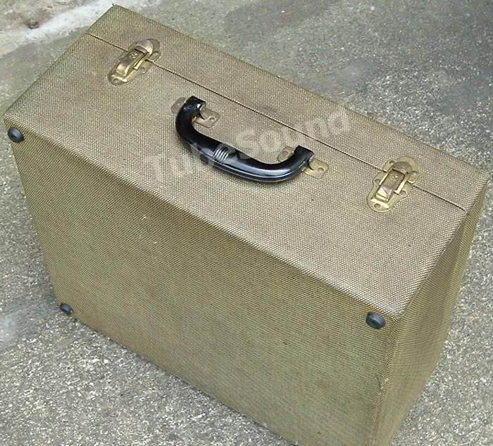
Build quality is very high. Beefy transformers, metal/wood cabinet, solid push buttons, quality switches and potentiometers, and smooth meter action all speak to the quality of the components.
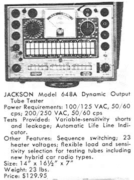
Physical size is somewhat large: 16.5 x 14.5 x 7 inches (42cm x 36.5cm x 17.5cm), weight 18-lbs (8.2Kg).
CIRCUITRY EXPLAINED
The Jackson 648 has 15 test configurations that select a preconfigured combination of Plate-Screen Voltage, Meter Shunt, and Plate Load, plus the ability to reverse the direction of the meter. (I have assembled a chart to explain these combinations.) These test configurations are the pushbutton letters V through Z, including any two-button combination (such as WY). Letter U reverse the direction of the meter when needed for a particular tube.
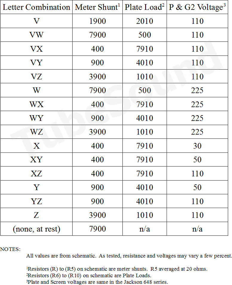
Resistors R through R5 on the schematic are meter shunts. Resistors R6 to R10 are plate loads.
The Plate potentiometer adjusts the meter sensitivity. The meter reads the tube’s DC plate current.
Notice that the Jackson 648 applies identical plate and screen voltages to the tube under test. The Screen Load (R11 on schematic, 5000 ohms) is the same for all tests.
Pressing Circuit D, button A, selects a grid voltage of 1 vac. Otherwise, the grid voltage is 5 vac.
All voltages in the Jackson 648 are AC.
REPAIR
Tools needed: accurate digital multimeter (capable of volts, ohms, milliamps), a variac, Caig DeoxIT cleaning solution, octal Test Socket, jumper wires, 1-megohm resistor, diode. Do not use a cheap multimeter because cheap multimeters have extremely poor accuracy. Use a quality meter of known accuracy, such as a Fluke. Otherwise, you are wasting your time.
To begin, I always remove the roll chart. This protects the chart from chemicals used during the cleaning process. Next, I carefully clean the entire tester, inside and out, and use my garage air compressor to blow dry. I observe whether any wires move from the high pressure of the compressed air (likely a broken connection), and follow that up by using needle-nose pliers to give a gentle pull on each connection.
Inspect line cord, and replace if not excellent.
Remove the internal 1S5 tube, clean its pins, and test this tube on another tube tester. Replace if weak or defective. Reinstall tube. (Alternatively, upgrade to solid-state and eliminate the 1S5 tube.) The 1S5 tube is very important — it’s sole function is to monitor the line voltage and allow you to properly ‘set the Line’. Alternatively, replace the 1S5 tube with my solid-state upgrade.
Next, check all resistors for accuracy, and replace those out of tolerance. To check many of these resistors, you will need to remove one side of the resistor from the circuit to achieve an accurate reading. I also replace the 0.1µF capacitor as a matter of habit.
The meter movement is 1 mA, 100 ohms. Speaking of the meter, I have found a low AC millivolts ripple across the meter on a number of units, enough of a ripple to cause the meter to chatter (although visually look unaffected). The ripple can be easily removed by connecting an electrolytic capacitor across the meter (anything in the 200µf to 300µf range will work great, voltage rating can be very low since this is only a millivolts ripple.)
Next, you must clean the Plate potentiometer, which is probably the MOST COMMON component source of inaccuracy and inconsistent readings. Remove the large round knob from the “Plate” potentiometer. Remove the nut affixing the potentiometer to the chassis. Once loose, look under the chassis and you will see an opening into the potentiometer, as shown in the next photo:
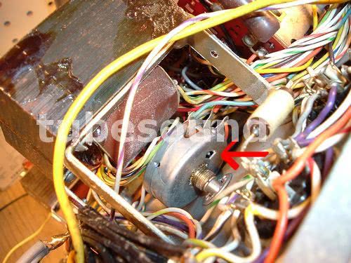
Into that opening, apply Caig DeoxIT (which is available in either drops or spray can). Turn the potentiometer clockwise-counterclockwise a number of times, then repeat once more. The DeoxIT will clean the potentiometer, which will then be extremely accurate. Reassemble.

Polish each socket pin individually to remove all of the dirt and oxidation. This takes a lot of time and effort but pays off when you are done. If any socket does not respond favorably, it must be replaced.
Treat all remaining potentiometers, controls, and switches with DeoxIT (including the push button contacts, the Grid Leakage potentiometer, Line control, Shorts switch). Treat R15 and R5 with DeoxIT also.
CALIBRATION
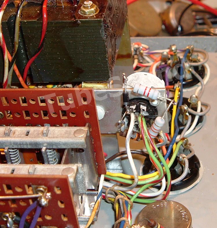
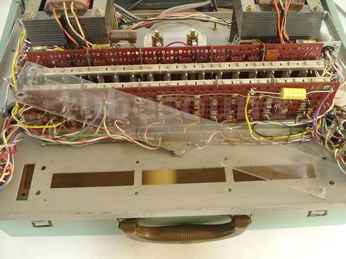
With power off, make sure that the panel meter is resting at exact zero, and adjust the setscrew if necessary. The following photograph shows the location of R15 and R5 inside the 648A model; the controls will be similar for other versions of the 648, but may be located different:

Line Calibration.
The Line Control is frequently far out of calibration, especially on the early 648 models that use the 1S5 tube.
The only purpose for the Line control is to accurately configure the tester’s secondary operating voltages (plate, screen, grid, filament).
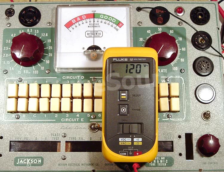
You will see a series of numbers on the Line Control, and these numbers correspond to the “mains” voltage (ie, your house line voltage). Setup your Variac for one of these voltages (such as 120), and plug the tester into the Variac. With the Line Control at 120, the meter should read perfectly centered on the Line mark. If not, disconnect power and adjust R15.
While that is the basic procedure, I now take it one step farther by checking the secondary voltages for accuracy, because that the only purpose for “setting the Line” anyway. I have noticed that in a few Jackson’s that the operating voltages are a hair low using the standard Line calibration procedure.
Configure the tester Circuit D “1 – 2 – 3”, Circuit E “4 – 5 – 6”. Using test socket in octal socket, voltmeter prods on pins 3 and 8, check the relevant secondary voltages. Pressing W = 225 vac, V or Z = 110 vac, Y = 50 vac, X = 30 vac. If you find these operating voltages are a hair low, (such as 221 vac instead of 225 vac), tweak your Line calibration to accommodate. In several testers, I have noticed that the mains voltage may need to be set approx 1.0 to 1.3 vac above the Line faceplate markings in order for the operating voltages to be “spot on.” These voltages are best checked with a quality DMM.
Optional: Quick and Easy Solid-State conversion for Line
You can eliminate the 1S5 tube and upgrade to the solid-state Line circuit using this quick and easy method that I developed. The benefit is that Line calibration should remain accurate by removing the issue of 1S5 tube aging/defects.
Parts needed: a common diode (1N4007, for example) and 41,200 ohm resistance.
- Remove 1S5 tube
- Connect cathode (banded) end of diode to pin 6 of 1S5 socket
- Connect anode end of diode to one end of 41,200 ohms resistor
- Connect remaining end of resistor to pin 2 of 1S5 socket.
- Perform the Line Calibration as described above.
(To read how Jackson implemented the solid-state Line in newer 648 models, click [HERE].
Plate Current Calibration (updated)

This chart[1] explains how much DC plate current will cause the meter to read half-scale (“Line”) using each Test Button and with Plate Control setting of either “10” or “50”. This is the meter sensitivity at half scale. A theoretically “perfect” Jackson 648 calibration would verify all ten chart entries. But since no antique tube tester was precision engineered, consider this chart your target.
In my experience, the plate current is usually quite accurate, and seldom needs much adjustment.
Method #1 — External DC power Supply method: The original calibration procedure[2] advises (with tube tester unplugged) to connect a dc milliammeter in series with an external variable DC power supply (+) to junction of R5 and R11, and (-) to pushbutton “X” clip on S4 switch, where you will find either a gray/white wire or black/white wire. The document uses the first chart entry as the calibration example (25ma when pressing “V” and plate control @ 10).
If you have a lower voltage DC power supply (with suitable current rating), set the Plate control @ 50, press V and verify 5.0ma. For all meter sensitivities with plate @ 50, your DC power supply only needs approx 11 – 15 volts. Check each test button V through Z.
Using method #1, if you want to check meter sensitivity with Plate control @ 10, your DC power supply must be capable of 60V at the currents specified in the chart.
Adjustment is made via R5, the 40 ohm variable resistor.
Method #2 — No external power supply required: I have created an alternative plate current calibration procedure for persons without a suitable DC power supply. This method only requires a variac, digital DC milliammeter, and 1N4007 diode.
Set variac at 0 (zero volts), and plug tester into variac. Power off. Configure Jackson as follows:
- Line control at 100
- Circuit D “1 – 2 – 3”
- Circuit E “4 – 5 – 6”
- Plate control @ 10
- Insert a test socket into the Octal socket.
- Calibration will be performed using Test Button V, Plate control @ 10, for a meter reading of “LINE” when 25.0 ma DC plate current is flowing.
Connect the diode anode end to octal test socket pin 3. Connect diode cathode (banded) end to the (+) lead of digital DC milliammeter. Connect (-) lead of digital milliammeter to pin 8 of test socket.
Variac should still be at zero. Power on the tester. Press and hold V button. Adjust variac voltage upward until DC milliammeter reads 25.0 mA. The meter should read mid-scale (LINE). Adjustment is made via R5, the 40 ohm variable resistor. (Power off tester before adjusting R5, then re-test accordingly.)
Several meter sensitivities are photographed below as examples. When testing a different meter sensitivity, always remember to return the variac to zero and start anew. This will avoid accidentally slamming the meter.


Keep in mind that no vintage tube testers were built with all precision components. For example, the plate control is not a precision engineered pot, so you may not get a “perfect” reading at all calibration points, although all will be very close.
I was recently asked whether Method #2 would result in a different calibration than Method #1, under the hypothesis that Method #2 uses pulsating DC, whereas Method #1 uses filtered DC. Implied in the question is that your dc milliammeter could read slightly different due to the AC ripple. I repeatedly tested each method using my Fluke 179, a cheap Greenlee DMM, and a budget “coupon” two-dollar DMM. Each meter read consistent for plate current calibration regardless of either method. I would also point out that when the Jackson meter is reading the DC plate current during a tube test, this plate current is pulsating DC anyway.
SHORTS TEST
I have created a chart to provide accurate checking of the Shorts Test functionality:
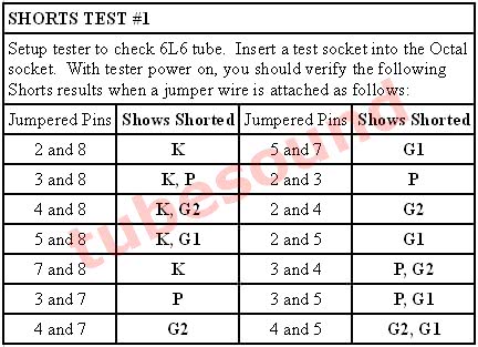

These tests are easiest to perform using a Test Socket and working from the front panel. You can quickly and easily move your jumper to each setting.

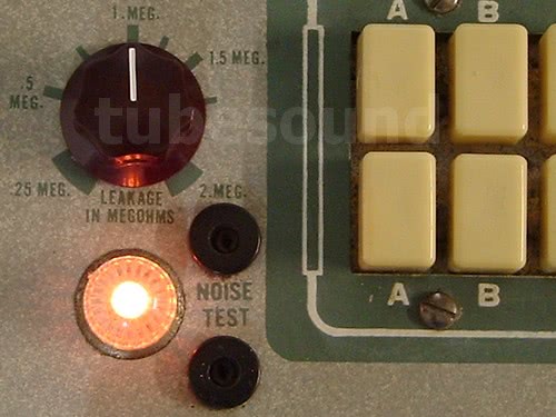
When you turn the Shorts Test switch, the Shorts light should illuminate in the positions noted in my Shorts Test chart above. If not, you have a continuity problem somewhere that you need to track down.

UNDERSTANDING HOW THE SHORTS TEST IS MADE, AND LIMITATION THEREOF
To further understand the Jackson 648 shorts test, you must realize that this tester analyzes each section (of a multi-section tube) independently, without reference to the other section(s). What does this mean? Each section is analyzed for shorts or leakage among only its own elements. This makes sense, as each tube section is treated like an independent tube. For instance, in a dual-triode tube, the elements of Triode #1 (cathode, grid, plate, heater/filament) will be analyzed against each-other, without regard for the elements of Triode #2. Thus, if a tube has developed shorts across sections, such as if a wire broke and created a cross-section connection, the Jackson will not detect that short.
For example, I will simulate a cross-section short of cathodes in a 6SN7GT. (I could have chosen any elements, such as plate #1 to plate #2, grid #1 to cathode of section #2, plate #1 to grid of section #2, etc). A 6SN7GT tube has 2 triode sections, with pin 3 the cathode pin for Triode #1 and pin 6 the cathode pin for Triode #2. Using an octal test socket, I have jumped together pins 3 and 6 to simulate a cross-section cathode-to-cathode short.


As you see in the photos (click to enlarge), cross-section shorts will not be detected (shorts light not illuminated in either Triode #1 or Triode #2 setup). That said, a cross-section short would be quite rare and nothing to give much thought about. I mention this limitation simply to compare that these shorts would be detected in a Sencore Mighty Mite TC162, TC28, or B&K 607 or similar tester that has 100% shorts detection accuracy because they compare each element against all other elements inside the envelope. Since it is unlikely that you would encounter a short of this nature, the point is really academic.
LEAKAGE TEST
You can check the accuracy of the leakage control by slightly changing your approach to the Shorts Test above. Instead of jumpering a solid wire between the pins as indicated on my Shorts Test chart, you will instead connect a 1-megohm resistor between the pins.

When turning the Shorts knob to those positions where my chart indicates “Short”, what you will see will depend upon the setting of the Leakage control. Starting at the 0.25 meg position, you should NOT see any glow in the Shorts light. As you slowly turn the Leakage control clockwise, the lamp should dimly glow at the 1 Meg position. As you continue to turn the Leakage control clockwise, the glow should become brighter.

If the Lamp does not accurately light at the position where the faceplate reads 1-Meg during this 1-Meg leakage test, the easiest solution is to reposition the knob on the shaft so that this 1-Meg leakage is accurately reflected on the faceplate. If repositioning the knob is not sufficient to achieve reasonable leakage calibration, then reexamine R13 (220K) and R17 (leakage pot).
You can see the difference between how the Lamp indicates Leakage (photo above), vs. a full short (next photo below):
VOLTAGE READINGS
Finally, you will perform a series of voltage tests, testing for proper voltages of Filament, Plate, Screen, and Grid.
Test configuration: use an octal test, Circuit D “1 – 2 – 3” and Circuit E “4 – 5 – 6”.
- Connect AC digital voltmeter to pins 2 and 7 of octal test socket to check all filament voltages for close accuracy. Start with 0.75 and rotate clockwise, checking your readings at each position. If your voltages are inaccurate, then you did not perform the Line calibration accurately or you are using a cheap DMM with poor accuracy. If any positions have no reading, then you either have a defective switch, broken wire, or open transformer winding.
- Move your DMM to pins 3 and 8 to check all plate voltages. Check each letter individually — Pressing letter V = 110 vac, W = 225 vac, X = 30 vac, Y = 50 vac, Z = 110 vac.
- Move your DMM to pins 4 and 8 to check all screen voltages. Check each letter individually — Pressing letter V = 110 vac, W = 225 vac, X = 30 vac, Y = 50 vac, Z = 110 vac.
- Move your DMM to pins 5 and 8 to check grid voltages. Meter should read 5 vac. Press letter “A” under Circuit D, and DMM should now read 1.0 vac.
FINAL TOUCHES
Polish all screw heads, knobs, and buttons. This really makes your tester stand out. Clean the Plastic window for the roll chart so that visibility is excellent. If the window is cloudy, you can replace it with a new piece of thin plexiglass, which will really make the roll chart look excellent.
Reinstall roll chart. Install new equipment feet if the old ones are not excellent. You can also touch up the white lines on the knobs, and install socket-savers (especially in the high-traffic 9-pin-miniature socket and octal socket).

Need a pair of new socket savers to protect your tube tester sockets?
Buy a pair of new manufacture socket savers: 1 each SS-8 (octal) and SS-9 (9-pin-miniature).
$29.99 free ship USA

Finally, we achieve a properly repaired, accurately calibrated, beautiful test instrument. One that you can be proud to own.
CLOSING THOUGHTS
Pros: As discussed above, the Jackson 648 series is a Quality test instrument. While my tube tester collection consists of more than 30 unique models and quite of number of premium Hickok, Weston, and B&K models, I have always considered the Jackson 648-series as one of my top 5 favorites when all factors are considered.
- High Build Quality
- Capable of testing a large variety of tubes (from antique 01-A to modern M2057 compactron)
- Respected test method
- Good shorts test (with minor exception that rare cross-section shorts are not detected)
- Intelligent calibration procedure allows consistent results across units.
- Tests rectifiers at high voltage (225 vac) and suitable for evaluating balanced plate sections in a filament-type rectifier tube.
Cons: No tester is perfect, so I offer a list of “cons” to consider. In my opinion, none of these cons are significant, although depending on your needs for a tube tester, these cons may be important to you.
- Line control adjustment steps in 2.5V increments. This is less than ideal, because if your present line voltage is between settings (for example, your line voltage at this moment is 121), you must choose to set the line at either 120 or 122.5. This will cause a slightly different tube test score than when your line voltage can be set “perfectly” (such as 120 line voltage can be set to 120 Line on the tester). Hence, you will only achieve “perfect” results when the line voltage can be set identical to one of these 2.5V incremental settings. As a workaround, you could run the tester from a variac, and make any slight adjustments. Personally, only someone being very anal would fret about this issue and the minor test result variation, but it is worth mentioning.
- The unit is not fused and therefore the transformers are not protected from overload. You can easily install a 1A fuse if you want.
- Not the best choice for someone who works primarily with sweep tubes. For example, most HAM rigs use compactron finals, so Ham radio guys would be better served with a Sencore Mighty Mite or similar.
- Size and weight make it less than ideal for persons doing repair work on-the-go, or persons who want a very small footprint on their workbench. Smaller and lighter models are available (Accurate Instruments models, Sencore Mighty Mites, LaFayette models, etc.)
- Not all 648 models have the same socket configuration, which means that earlier models require socket adapters (or self-installation of new sockets) to test newer tube configurations, such as for novar and compactron tubes.
Food for Thought: Over the years, I have only met (in person) three guys who were truly world-class technicians. The real deal — guys who could design and fix just about any tube gear, regardless of whether it was sophisticated laboratory recording gear, military radar gear, whatever. Two of these guys worked in the top-top design labs of America’s old companies (Westinghouse and US Steel.) Fact is that 2 out of the 3 guys relied upon a Jackson 648A as their primary tube tester in the lab, and the 3rd guy used a B-K. Yes, there was other laboratory-grade tube test equipment available to them, cost was not an issue, but the Jackson is what received the overwhelming majority of use. In fact, the 648A’s that I bought from those guys were so worn out that almost all of the printing on the faceplates had worn away. On one unit, the shorts switch (which has a snap-action for each position) was actually worn smooth — it just twisted to each position without any snap action at all. And yet, while those Jackson’s looked like crap, they were still working perfectly. I can’t think of any better compliment for the Jackson 648.
How Long Does a Calibration Last?
Since posting this article, many people have asked how long a calibration lasts (before the tester will need recalibrated). This is an impossible question to answer, but I can explain which factors most influence the calibration.
For the early 648 models (such as the 648 and 648A), the condition of the 1S5 tube directly relates to the accuracy of the Line Control Calibration. As the 1S5 tube ages, or develops a defect, the Line Control will become inaccurate. This is the most common source of inaccuracy after a complete calibration has been once performed. This problem is easy to spot (the Line control will not precisely correspond to the AC line voltage), and easy to recalibrate. Just keep in mind that installing a new 1S5 will not solve your problem, you will always need to recalibrate the Line. Alternatively, upgrading to a solid-state Line is easy.
Next, component failure could occur. Typically, this would be resistors changing value. Obviously, you will not have any notice when this is going to happen. Assuming diligence in your restoration, this is a less-likely situation.
Finally, continuity issues relating to the switches/buttons and sockets. At a minimum, you should clean switches and sockets at least once a year (more often if you are a power user) and treat them with Deoxit. This is good practice and should be considered part of regular maintenance.
Reduce the wear on your tester sockets — Get in the habit of never testing tubes with dirty or rusty pins until you have completely cleaned the tube pins first. This will also increase the accuracy of your tube testing, because dirty or rusty tube pins can significantly affect the accuracy of the test result.
regards,
Bob Putnak.
eBay ID = rjputnak

MISCELLANEOUS DOWNLOADS:
Jackson_Technical_Bulletin_32-42A – constructing a picture tube test adapter
Footnotes:
1 Plate current values referenced from Jackson Model 648 Complete Tube Tester Manual (Second Edition), 2005, pp. 81. [Back to post]
2 Calibration procedure using an external metered DC power supply. Id. at 78. [Back to post]