
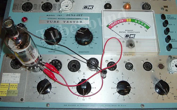
©2008, Bob Putnak. All rights reserved. This article discusses the B&K 707 Dyna-Jet Dynamic Mutual Conductance tube tester, including repair and calibration. The discussion is also relevant to the B&K 700 (the 700 is almost identical except for socket configuration) and some of the information is applicable to the B&K 650.


The B&K 707 tube tester dates from the late 1960s into the 1970s. My manual is stamped August 1969, and a modern tube data setup chart dates 1978.
First of all, a brief explanation of the circuitry of this tester is necessary. Is this a Mutual Conductance tube tester? Well, yes and no.
Tubes that test in the “Jet-Check” section test for mutual conductance, with the exception of diodes/rectifiers (which always test only for Emission). The Jet-Check section is the upper panel (sockets 1 – 35). Tubes that test in the “Switch” section — the bottom panel (sockets 36 – 45), are tested for Emission.
What does this mean? Well, for example, a 6146 tube is tested for Emission, not mutual conductance (Gm). So, if someone tells you that they tested a 20LF6, 6KD6, 6CW4, 6DS4, 6JS6C, 7868, 6146, etc… for good mutual conductance with a B&K 707/700, then they have no idea how to use and interpret the results from their B&K 707/700. This would include most sweep tubes (all 12-pin compactrons), all loctal tubes, most Novar tubes, all Nuvistors, and many octal and 9-pin-miniature tubes. A notable sweep tube exception are the 6LQ6-based tubes that test for Gm via upper panel socket #35.

That said, many popular audio tubes are tested for mutual conductance in the upper panel Dyna-Jet sockets. This includes such classics as 6L6, 6V6, 6550, 6CA7, 12AX7, 12AU7, 6SN7, 6SL7, 12BH7, 12AY7, etc. Probably a majority of our favorite audio tubes can be tested in one of the pre-configured Dyna-Jet sockets.
The beauty of the B&K 707 are these Dyna-Jet sockets. They allow rapid testing of multi-element tubes without any configuration. For example, say that you have 20 6SN7 tubes to test. In the B&K, you simply insert each tube into socket 25, turn the shunt dial as directed, and you can perform Shorts, Grid Leakage, Triode 1, and Triode 2 tests all by the press of their respective buttons. To perform a similar test in a Hickok, consider the procedure for a Hickok 6000. First, you would have to locate 6SN7 on the chart. Second, you would have to setup the heater voltage and connections (6.3, H Y). Third, you setup each element for Triode #1 by turning five knobs to 4-5-0-6-0. Fourth, you need to set the Bias (23) and Shunt (79) dials. Fifth, you insert the tube, adjust the Line rheostat, check visually for shorts, then make gas test. Sixth, you can finally press test button and get a reading for Triode #1. Seventh, you then have to decide whether you want to pull this tube out, and start testing all your other 6SN7’s Triode #1, or do you want to reconfigure the tester for Triode #2, which will include totally different positions for the Grid, Plate, Screen, Cathode, and Suppressor. If you reconfigure, you will have to do this at least 20 times to test all 20 of your 6SN7 tubes. (Assuming that you test T1 then T2, T2 then T1, T1 then T2, etc…) And many tubes will require changing the Bias and/or Shunt dials for each additional element. As you can see, this process is quite time-consuming. With your B&K, the process is effortless. You save a large amount of time and work. Thus, it is easy to see why the B&K 707 is favored by “power users” (anyone who sells or collects a large quantity of tubes).
“Switch” Section (the Emission section)
In the lower “Switch” section, the controls are:
- A & B = Filament connections
- C = Lockout switch. This switch will lockout (open) one pin, with the pins being standard RTMA numbered (switch position 1 opens pin 1, switch position 2 opens pin 2, etc.). If no pin needs to be locked out, then position 12 is selected. Typical lockouts are (a) control grid has connection to 2 pins, the higher numbered pin gets locked-out; (b) tubes with additional heater tap, such as 35W4; (c) the Shell pin of metal envelope tubes (often pin 1, example 6SA7).
- D = Selects the control grid for Emission test and grid leakage test. For diode and rectifier tube sections, ‘D’ selects the Plate pin. Also, Control D is rotated to every position during Shorts testing. Shorts test is automatic at each switch position — there is no need to press the ‘Shorts’ button on the upper panel.
“Switch Section” Shorts Test
In this Switch section, the Shorts Test places approx 100 VAC between the selected pin number at Switch D and all other elements. When a short is detected, the neon lamp will automatically light. The 100 VAC will be higher without any tube in socket, and a little lower when a tube is being tested.


This Shorts test is NOT perfect because the tester does not have a full selection of lockout switches. When testing tubes that have multiple tube elements with multiple pin connections, actual shorts can be missed.

Consider as an example tube 36KD6: control grid is connected to pins 5 & 9; screen grid is connected to pins 3 and 11; suppressor grid connected to pins 4 and 10.
The B&K chart settings are:

The first thing to notice is that Pin 9 is locked-out, therefore there will be no false shorts to the control grid. That is good. But the chart also explains that regardless of what is going on at pins 3-4-10-11, the Shorts lamp will light. This can be a problem.

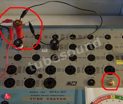
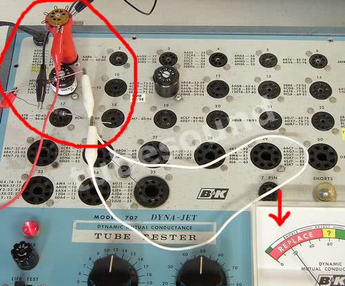
In the photo, pin 11 shows short with a perfectly good 36KD6 tube because pin 11 is internally connected to pin 3, and the chart explains that you can disregard this as correct behavior (which is correct in this example):
In the photo, I have connected a jumper wire between Pins 10 and 11, thereby shorting the Screen Grid and Suppressor Grid. While the Shorts lamp is still lit at Pin 11, the problem is that the chart tells you to disregard this short (because of the example in the left-side photo.) Therefore, since the tube tester behaves the same in both instances, you cannot know whether the tube has a short between those elements are not.
In summary, these B&K will not detect all shorts in tubes that have multiple elements connected to multiple pins. The most common of these tubes are Ham-Radio style sweep compactron tubes, examples being 6KD6, 6GE5, 6HF5, etc. This is a minor limitation, and one that is shared with most tube testers regardless of brand or cost. If your tester does not have a full row of lockout switches such as found in a TC162 Mighty Mite or B&K 607, then you also have this Shorts test limitation.
CHART “FALSE SHORT” WARNING: Note that many 12-pin duodecar tubes manufactured by Sylvania connect pin 7 to the center of the heater/filament. Examples would be 36KD6, 49KD6, and others. The B&K chart does NOT warn of a “Short” at pin 7 on these tubes, even though the basing diagrams reserved Pin 7 for “IC” (internal connection). Therefore, many users throw away perfectly good duodecar tubes because they “find” a short at position 7 (and also pin 12, the heater return), and since the chart does not tell you to disregard it, the user believes that it must be a tube defect. Wrong. Pin 7 is normally not used for anything in those tubes, but Sylvania did use pin 7 internally for a center connection to the heater. If you examine the tube you will easily see that pins 1 and 12 connect to the ends of the heater, and pin 7 connects to the center of the heater. Therefore, it is a FALSE SHORT. I would guess that if I had a dollar for every duodecar tube erroneously discarded over the past 30+ years because of a “Pin 7 short” tested on a B&K 700/707, I might have quite a retirement fund by now! Again, this is why you have to know your tubes. Even the best tube test equipment will not tell you everything that you need to know. There is no substitute for experience.
“Switch Section” EMISSION QUALITY Test
Emission Quality is not to be confused with “Grid Emission”. In this Emission test, approx 60 VAC is connected between control grid and cathode, and this test evaluates the ability of the tube to rectify the AC voltage into DC. (For rectifiers and diodes, the test method places AC voltage between the plate and cathode.) If you measure this AC voltage (between control grid and cathode) while testing a tube for Emission, the measured AC voltage will be lower than 60VAC.
The load resistance is 1,000 ohms, and can be quickly determined (tester powered off) by using a test socket in socket #38, ‘D’ switch at position 5, and measuring the resistance between pins 5 and 8 while pressing “Test 1”. You will measure approx 1,100 ohms. This is not a precision resistance because you are testing through the entire circuit but close enough to get an idea. The Sensitivity pot adjusts the meter sensitivity for each tube.
“Switch Section” GRID LEAKAGE Test
The switch section Grid Emission test puts the control grid negative to all other elements (which are all grounded). The voltage as tested between G1 and any other element is more than -70 vdc, biasing the grid beyond cut-off. If the tube has any grid emission, positive voltage will build across the 5.6 meg resistor that is part of the 6BN8 grid circuit. This positive voltage removes the cutoff bias of the 6BN8 tube and causes the meter to deflect, thereby showing grid emission.

The factory setting for Grid Emission sensitivity is 25 meg, but can be recalibrated more sensitive using a 100 meg resistor if desired, making it on par with a Mighty Mite.
Jet-Check Section (Mutual Conductance panel)
The Jet-Check section is the only place where any tubes are tested for mutual conductance. (Rectifiers and Diodes are always tested for Emission, of course).
“Jet-Check Section” GRID LEAKAGE and SHORTS Test
Grid Emission and Shorts are best discussed together because shorts may be detected by either SHORTS test, or GRID EMISSION test, or sometimes both tests.
Using Socket #29 as an example, when pressing the SHORTS button, the (approx) voltages are:
- P to K (ground) = 145 VDC
- G2 (Screen) to K = 0 VDC
- G1 (control grid) to K = -72 vdc
- The socket connects both Cathode and Suppressor pins to ground, so the voltage is zero.
When pressing the GRID EMISSION button, the voltages are:
- P to K = 145 VDC
- G2 to K = 145 VDC
- G1 to K = -72 vdc
Let us connect a jumper wire across every combination of tube elements at Socket 29, and see “how” this short is detected. (Since the suppressor grid pin and cathode are both grounded at the socket, the suppressor is not considered separately.)
- H (heater) to P — SHORT = nothing; GRID EMISSION = neon lamp glow
- H to G2 — SHORT = neon lamp glow; GRID EMISSION = neon lamp glow
- H to G1 — SHORT = full meter deflection; GRID EMISSION = full meter deflection
- H to K — SHORT = neon lamp glow; GRID EMISSION = nothing
- P to G2 — SHORT = neon lamp glow; GRID EMISSION = nothing
- P to G1 — SHORT = full meter deflection; GRID EMISSION = full meter deflection
- P to K — SHORT = neon lamp glow; GRID EMISSION = nothing
- G2 to G1 — SHORT = full meter deflection; GRID EMISSION = full meter deflection
- G2 to K — SHORT = nothing; GRID EMISSION = neon lamp glow
If you substitute a 1-meg resistor in place of the jumper wire, the results will be the same, except that the neon lamp will not glow as brightly.
However, if you substitute a 10-meg resistor in place of the jumper wire, this leakage will ONLY be detected between G1 and all other elements (including the heater pins), and will be detected as full meter deflection when either SHORTS or GRID EMISSION button is pressed.
LIMITATION OF SHORTS & GRID LEAKAGE TESTS IN JET-SECTION: It is interesting to note that when testing multi-section tubes in one of the Jet-Check sockets, such as 12AX7, 5U4GB, or 6AN8, you need to understand that Shorts or Leakage between same-element across the two sections will not be detected. This is NOT a big deal, because this type of short would be extremely rare. There would have to be a small piece of metal broken off inside to cause the short.
For example, insert a test socket into socket #9 and jumper pins 2 and 7 together. This simulates a short between the Grid of Triode #1 and Grid of Triode #2 of a 12AX7. Notice that this short is not detected by pressing either SHORTS or GRID EMISSION. This limitation will occur with any Plate to Plate short, K to K short, Screen to Screen short, G1 to G1 short between sections.
I mention this limitation simply to compare that these shorts would be detected in a Sencore Mighty Mite TC162, TC28, or B&K 607 or similar tester that has 100% shorts detection accuracy. Since it is unlikely that you would encounter a short of this nature, do not worry.
WORKAROUND: If you really want to be 100% sure, you can make an additional SHORTS test for these dual-section tubes in the BOTTOM “Switch Check” section. As explained above, the bottom section will test each pin against all other pins. (While the bottom Shorts test is not perfect, as explained above, its limitations are not relevant to the types of tubes you can test in the Jet-Check section.) Use an RCA receiving tube manual to determine how to setup the tube — all you need is the basing diagram and the correct heater voltage.
For example, to test a 12AX7 for shorts in the bottom section, you would use socket #39, heater voltage 12, A = 4 (heater pin), B = 5 (the other heater pin), C = 9 (basing diagram shows a center tap on the heater at pin 9, so you need to lockout pin 9). The D switch will then be rotated to each position. In our example above, when I shorted pins 2 and 7 with a jumper wire, this short would be correctly detected at position 2 and 7 of D switch.
Jet-Check Mutual Conductance Quality Test (and Emission Test for diodes and rectifiers)
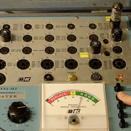
The transconductance test uses a signal voltage of 1.5vac, which is varied slightly by the ALC circuitry to compensate for line voltage fluctuations. The filtered DC bias will vary depending on the socket, with nominal values being (-19.5 vdc, high bias), (-7.5 vdc), (-2.5 vdc), and (-0.2 vdc low bias, typically measures essentially zero). Plate voltage is a little above 200 VDC pulsating, screen voltage approx 160 vdc filtered. The meter scale has no provisions to determine a micromhos score. The scale is numbered 0-120, with approx 65+ considered good and 100 reference for a typical new tube.
Each Jet-Check socket is designed to test all tubes that have a compatible basing diagram. That is important to understand. The sockets were NOT designed to test tubes with the same operating characteristics. This is a big limitation of the Jet-Check mutual conductance sockets because each socket provides a “one-size-fits-all” test (with the minor exception that the heater voltage can be varied), meaning that each socket has one FIXED set of parameters (same plate voltage, same screen voltage [if relevant], same bias, same signal voltage). These parameters cannot be changed, even though a variety of tubes with substantially different operating characteristics are all being tested in that same socket.
For example, socket 8 tests a large number of tubes — 6922, 12ax7, 12au7, 12at7, 6FQ7, 12bh7, 6bz7… to name a few. Each of those tube types have SUBSTANTIALLY different operating parameters — just read an RCA tube characteristics manual. But, the B&K does not tailor an individual test to them. Because those types all share a similar (compatible) basing diagram, they are each tested in socket #8.
The problem is that those tubes are NOT interchangeable with any degree of performance satisfaction — but they are being TESTED with identical operating parameters.
For example, you can’t swap a 12AX7 with a 12BH7/12AU7/12AT7 etc… in most circuits and expect the equipment to perform the way it was designed — if it performs at all.
You simply cannot bias each of those tubes identical and expect each of them to be operated in the linear portion of their characteristics curve. A test that does not drive a tube in the linear part of its characteristics curve is a substandard test and may not accurately represent its condition because the tube is not being operated in a way that is similar to how it will be operated in a “real circuit.”
Hence, each Gm Jet-Check socket is a HUGE compromise in test parameters for many of the tubes that are being tested in that socket. In socket 8, for one example, the parameters are fine for testing a 12AU7 but substandard for a 12AX7. In socket 29, the parameters are acceptable for testing a 6L6 but a 6V6 is not driven very hard at all. In socket 23, a 6BQ5 is driven light. Those are a handful of examples.
Hence, the Jet-Check mutual conductance sockets are a design compromise to achieve SPEED of operation and SIMPLICITY of use. Ideal test parameters were sacrificed to achieve those goals.
Having explained that, a seasoned technician can easily get a feel for which tubes are being driven with substandard test parameters (either being overdriven, such as a 6922, …or underdriven, such as a 6BQ5), and can get a feel for how a substandard tube will test based upon experience with testing other tubes of same type that were underperformers in a real circuit. This is when “real-world-experience” and “knowing-your-test-equipment” is of utmost importance.
The emission test for Diodes and Rectifiers, such as 5U4GB, applies approx 35-38 VAC to each plate.
REPAIR AND CALIBRATION
All voltage tests below are made at 117V line voltage. Tester should be connected to a Variac set at 117 vac for all calibration procedures that require voltage readings. Photos here reflect 117vac Line.

Do you need service manual, schematic, and modern tube setup chart for your B&K 707?
Remastered paperwork package for the B&K 707, which consists of service manual, schematic, and modern 1978 tube setup chart with several mistakes individually corrected by me.$13.99 free ship USA.

Need a pair of new socket savers to protect your tube tester sockets?
Buy a pair of new manufacture socket savers: 1 each SS-8 (octal) and SS-9 (9-pin-miniature). $29.99 free ship USA.
These SS will work in all applicable B&K sockets except for those without a center hole to allow the socket saver screw to pass through, such as socket #39 B&K 707
First, a good cleaning of all the electronics is a must. Blow dry with a garage air compressor.
Adjust the setscrew on meter face so that panel meter rests at Zero.
All sockets, switches, and potentiometers (including the Sensitivity pot) should be cleaned and treated with Deoxit, and rigorously worked clockwise / counterclockwise. The Sensitivity pot is sealed and must be carefully pryed open and treated with Deoxit.
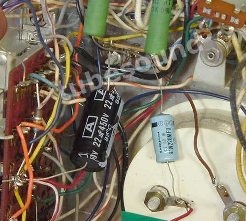
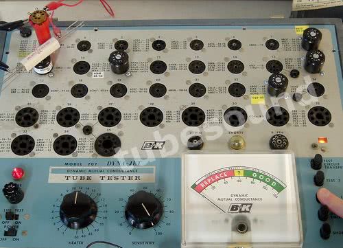
Any sockets that are very loose at holding the tube must be replaced. Popular sockets such as #8, #25, #29, #33, #35, #38, #39, and #41 should be closely examined; they are high-traffic and most likely to be worn out. After replacing, install socket-savers to protect new sockets. The following picture shows 3 new sockets that I recently replaced (the white ceramic sockets are the new ones).

Second, resistors must be individually checked for accuracy. Resistors that cannot be checked in-circuit must have one-end removed and rechecked. No shortcuts here.
IMPORTANT FACT REGARDING B&K METERS: The meter circuit is designed for 1 ma F.S. and 100 ohms resistance. However, not all B&K meter movements have this spec. Many B&K 700 and B&K 707 were shipped with a meter movement that is 1 ma F.S. with 40 to 42 ohms resistance. Many other B&K 700 and B&K 707 were shipped with a 1 ma F.S. 100-ohm meter movement. In my own B&K 700’s (6 units) and 707’s (5 units), I have five testers that have the 42-ohm meter movement (4 – B&K 700, and 1 – B&K 707). Interestingly, all testers that I have seen with the 42-ohm meter movement were also supplied with a transformer that is marked “TP-26”. I think this was a supply-chain issue because there is no technical correlation.
There are no full-proof markings to differentiate a 42-ohm meter from a 100-ohm meter. While most of the 42-ohm meters seem to have a faceplate that is marked “ME-12-M”, I have seen several “ME-12-M” faceplates on 100-ohm movements. Therefore, the meter must be tested to know which movement you have.
This issue of different meter movements is not documented at all on the B&K 700 schematic (which does not show a 56-ohm series resistor), and the B&K 707 schematic is misleading because it shows a 56 ohm resistor in series with the meter movement, thereby assuming a 42-ohm meter movement. If you are following along, this is quite interesting dichotomy — the B&K 707 schematic assumes a 42-ohm movement, but only one of my five B&K 707 testers actually have the 42-ohm meter movement. The B&K 700 schematic assumes a 100-ohm movement, but four of my six B&K 700’s have a 42-ohm meter movement with 56-ohm series resistor. Go figure!
Again, realize that the 56-ohm series resistor is ONLY used in a tester that shipped with the 42-ohm meter movement. Units that shipped with the 100-ohm meter movement do not, and should not, have the 56 ohm resistor installed. I have seen B&K 700 and 707 that test low and this is often the problem. Someone either adds this resistor to a 100-ohm meter because they saw it on the schematic, or they replaced a 42-ohm meter with a 100 ohm meter, and did not know to remove the resistor.
Finally, if you have the 42-ohm meter movement, be sure to check the value of the 56 ohm series resistor because it often drifts up in value. In fact, for best accuracy, put your millivolt meter across the meter movement, see exactly what it checks with full-scale deflection (typically 40 to 42 mv), subtract that number from 100, and adjust the series resistor accordingly. For example, if you see 42 mv full scale, then 58 ohm series resistor would be the “perfect” value.
Third, all capacitors should be replaced (preferably), or at least tested on a quality capacitor tested and reinstalled.
Fourth, test both internal tubes (6BN8 and #83) on another tube tester. The #83 should have both plate sections closely balanced emission (if not, replace.) The #83 can also be replaced with a Solid-State substitute.
Fifth, I would mention that possibility of soldering the #55 bulbs directly into the circuit and not relying upon the bayonet lamp sockets to give you consistently perfect continuity. Why? Well, anyone with sufficient experience repairing vintage pinball machines and antique jukeboxes will know the problems associated with these old bayonet lamp sockets. They suck. No matter how much you clean them, they are 50+ year old sockets and continuity will falter occasionally — a flicker here, a blink there… sometimes a little, sometimes a lot, sometimes after extended warmup, sometimes when cold. May not happen for a few weeks or months after you have cleaned them, but it seems to always eventually happen. And these #55 bulbs are critical to the ALC (automatic line control) circuitry, so you NEED perfect continuity here. This “eliminate the sockets” subject has long been my opinion to ensure a long-lasting calibration, but occasionally I am asked if this really must be done if the sockets are known to have good continuity. No… if the sockets are working well, then of course you can leave them alone for now.

The #55 bulbs almost never go bad (I have not had to replace mine in 18 years of every-day use that I have owned this tester, and they are probably original and pushing 50-60 years of usage. The bulbs should be of equal brightness, and when possible, from same manufacturing lot. If either bulb needs replaced, use only NOS USA inventory (no imported junk) and replace both from the same NOS box lot.
Sixth, check the accuracy of the Shorts Test function. First, with all sockets empty, push SHORTS button and make sure that the shorts light is not lit. (If it does light, you have a short somewhere that must be located before proceeding.) Next, using a Test Socket in socket #1, connect a 1-Meg resistor from pins 2 to 4. Power on tester, allow 15 minutes warm-up time, and press Shorts button. The Shorts bulb should barely light. Adjustment is made via R16 (accessible through socket #30).
Some users prefer to set the Short Test at 2-Meg sensitivity. If that is your preference, adjust accordingly. Personally, 1-Meg has been the accepted standard, so I use 1-Meg. Furthermore, many power tubes will show a slight glow at a 2-Meg sensitivity, so unless the user is savvy enough to properly interpret the results on a sliding scale based upon their knowledge of the tube-type being tested, a 1-Meg sensitivity is really the ideal choice.
Seventh, check the Grid Emission functionality. With all sockets empty, press GRID EMISSION button and check that the meter does not move, and that the Shorts light does not illuminate. (If so, you have short or leakage developing somewhere and must be located before proceeding.) Next, reinsert the Test Socket, and connect 20-Meg resistance (you can use two 10-meg resistor in series) between pins 1 and 7 of your test socket still in socket #1. Allow tester to warm up for 15 minutes, Press Grid Emission button, and meter should read near 20 on the scale.
Adjustment is made via R18 pot, accessible with a screwdriver thru socket 33.
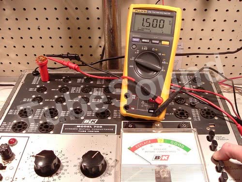
Eighth, check the Signal Voltage.
Make sure tester is connected to a Variac set at 117 vac. Connect a quality Fluke meter to pin 1 (pos) and pin 2 (neg) of your test socket in socket #1. Set the meter to autorange AC voltage. Press TEST 1 button, read 1.5 AC volts.Adjustment is made via R20 pot, accessible thru socket #25.

Ninth, check DC Bias.
Using same setup as above, set Fluke meter to autorange DC voltage. Press TEST 1, observe (-2.5 ) DC volts.

Adjustment made via R11 pot, located inside the tester beside the 6BN8 tube on the transformer bracket.
Tenth, check BALANCE CONTROL. Connect a 10-watt, 10K ohm resistor between pins 5 and 2 of the test socket in socket #1. Set Sensitivity Control to 100. Press TEST 1 button, meter should hover on Zero. (Yes, the manual instructions use a 6K resistor for this test. That will work, but using a 10K is better.)
If meter deflects either direction, adjust R5 (while depressing TEST 1 Button) until meter balances perfectly at 0. Power off, and remove test socket. I have found on several occasions that R5 can have unsatisfactory performance even after treated with deoxit, and must either be replaced or substituted with fixed resistors (start with a matched pair of 10 ohm resistors, and shunt one of them with approx 220Ω until balance is achieved). Unless R5 is stable, as your balance goes off, so will your test scores.
Eleventh, test DC plate voltage. Plate voltage can be tested using octal test socket in socket #29, positive lead of Fluke to Pin 3, Neg lead to Pin 8. Press TEST 1 and observe result.

The Gm plate voltage is supplied by a high voltage transformer secondary winding, and full-wave rectified by the #83 vacuum tube. This circuit supplies pulsating DC voltage to the tube’s plate during a mutual conductance test. I recommend replacing the #83 vacuum tube with a modern solid-state #83 fused conversion module.
Need a quality solid-state #83 upgrade?
We offer a premium version of the #83 solid-state upgrade that is fused to protect your transformer. Yes, solid-state diodes are reliable but they are known to short occasionally, and you will be happy that you bought our fused #83 solid-state upgrade instead of a cheapass unfused module. Price $19 free ship USA
Twelve, test the rectifier plate voltage — approx 35 vac and tested at socket 33 (pins 4 to 8 pressing TEST 1, then pins 6 to 8 pressing TEST 2.)

Thirteen, test DC screen voltage. Screen voltage can be tested using octal test socket in socket #29, positive lead of Fluke to Pin 4, Neg lead to Pin 8. Press TEST 1 and observe result.

This completes basic calibration checks, but keep in mind that these units were not built with laboratory precision — you will find that the transformer plate and screen voltages are not perfectly uniform from machine to machine, the sensitivity pot is not a precise component, and even the panel meter has some good old analog variation to it. If “best” accuracy is critically important to you, a final check should be made using a stable 6L6 calibration tube from a reliable source (no ebay garbage, and sorry but I do not sell calibration tubes because it is hard to find tubes that test consistent and repeatable on many different makes & models of tube testers, which is the only kind of calibration tubes that I will use…). Use of a calibration tube may show that tweaking of the signal voltage or bias may be required. But for most people’s needs, the basic calibration procedure is sufficient.
UPGRADES / MODS
There are several upgrades that I have performed on my own 707.
- install back-to-back diodes across the meter movement, to help protect the meter from overloads which could happen from mistakes in tube setup config, shorts, or other miscues. The standard choice is 1N4007 back-to-back, which I have used for almost two decades with good success. [2023 update: Mr Carlsen (from Mr. Carlsen’s Lab) has suggested that STTH3R06 diodes may be an even better choice, having a bit lower forward drop than 1N4007 but still without effecting meter readings.]
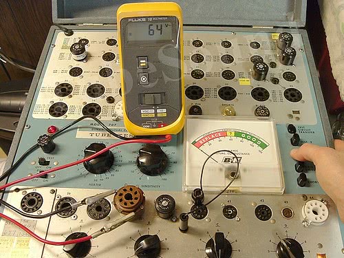
- custom digital Gm plate current meter installed into the front panel (see photo at top of this article). This allows you to easily see the tube’s operating point during testing. (2023) I have now improved the mod so that the meter also reads the operating current during the bottom-panel emission test, too.
- Gm compactron socket installed. Socket 34 removed, replaced with compactron socket for Gm testing of popular Ham sweep finals including 6JS6C, 6LB6, 6KD6, 6LR6, 6HF5, 6LX6, 6LF6, 6KN6. Plate current levels are typically 75-90ma. Wiring is easily determined from an RCA tube guide and tapped from the adjacent novar socket #35. Acceptable “Sensitivity” settings can be found using the values found on a B&K 747 data chart.
- 7591 Gm socket. Socket 32 repurposed for Gm testing of 7591 output tube. I use (-2.5 vdc) bias, which drives a quality NOS 7591 to approx 35-40ma plate current, plate dissipation approx 8 watts. Testing my inventory of USA NOS 7591 / 7591A tubes, a “sensitivity” setting of “42” was an average to get a reading of “100” for the best 7591’s in my inventory (with plate current of 40ma typical.) Used 7591’s that were known to have substandard power output when tested in an amp, each tested correctly much lower (approx 50 – 70 on the meter) and with significantly lower plate current (15-23ma), with acceptable-used 7591’s testing in the 80s and having plate currents in the high 20s to low 30’s ma. If you use 7868 tube (which is essentially the same as 7591), the same mod could be made using a novar socket and wiring accordingly.
- 6BQ5 Gm test upgrade. Socket 23 was obviously designed for testing 6CW5 because a 6BQ5 is not driven enough for a “good” test (typically 20-23ma plate current for a quality NOS 6BQ5). Removing the 82-ohm cathode resistor on this socket, and grounding the cathode, will drive a top quality NOS USA 6BQ5 to approx 38-40ma plate current, plate dissipation approx 8 watts, and an average Sensitivity setting of “40” represented a reading of “100” for these best-quality 6BQ5. The lowest NOS 6BQ5 tested in the high 80s and read 33ma plate current, with most NOS falling in the 90s and with a plate current of approx 33-38ma. NOTE: this mod removes the ability to test 6CW5 in this socket, as a 6CW5 will overdrive to 90+ma plate current. In my opinion, since 6BQ5 is a much more common and popular audio tube, sacrificing 6CW5 testing is a minor nuisance to achieve a much better 6BQ5 test.
- 5687 Gm socket. Socket #19 repurposed for Gm testing of 5687 dual triode, which has become a reasonably popular tube in the audiophile community. Each triode is tested individually. I use -7.5 vdc bias supply and a 47-ohm cathode resistor with Sensitivity setting of “69”. These parameters consistently drive an NOS USA 5687 tube to an average meter reading of “100”, operating at 20ma plate current per triode and with approx 3.6 watts plate dissipation (still within maximum design rating).
- 5879 Gm socket. Socket #18 repurposed for Gm testing of 5879 pentode. I do a lot of Seeburg jukebox amp repair, and 5879 is a popular preamp tube. I use a triode configuration (P,G2,G3 connected together), -2.5 vdc bias supply, a 470-ohm cathode resistor, and Sensitivity setting of “100”. These parameters drive an NOS USA 5879 to approx 6ma plate current and 1-watt plate dissipation (which is within the 1.25W design max). Meter readings of 40+ indicate a good 5879.
- 6BM8 Gm socket. Socket #15 repurposed for 6BM8 ECL82 Gm testing. Test #1 wired for pentode section using -7.5 vdc bias which drives NOS 6BM8 at 30ma to 32ma plate current, average Sensitivity set to “55”, plate dissipation slightly under 6W. Test #2 wired to test the triode section using -0.5 bias supply and 120-ohm cathode resistor. This drives the triode section with 4ma plate current, 0.7W to 0.8W plate dissipation, average Sensitivity set to “94” for the Soviet 6F3P tube’s triode section to read 100. Vintage-manufactured Japanese and European 6BM8/ECL82 seem to need an average Sensitivity of “90” for a meter reading of 100, otherwise they will push the limits of the meter. I feel that both sections are being driven within realistic parameters and without over-driving. Since my test sample size is somewhat limited at this time, I will revisit the Sensitivity settings when I acquire more NOS 6BM8 of different brands.
- new 12AX7 socket. I do not use the exact “12AX7” upgrade that some guys have asked me about. While the default 12AX7 test is not ideal, I find that it is excellent at finding substandard 12AX7 tubes, which is all that a tube test is really meant to accomplish. Due to my approx 30 years of using a 707 and testing thousands of new & used 12AX7’s in socket #8, I have no problem interpreting these test results. The basic mod involves repurposing socket #24 for 12ax7 testing and using “Low Bias” instead of the default bias. In my opinion, this mod only works well if you take the effort to modify the tube tester’s bias circuitry to make the low bias 0.5vdc as it is on the B&K 747. By default on the 700/707, the low bias is much hotter (lower voltage). With the low bias modified to 0.5 vdc, then I feel this is a worthwhile upgrade.
FINAL THOUGHTS
The B&K 707 is the ultimate professional-grade tester for:
- a shop technician who services tube gear on a regular basis, allowing fast screening of tubes with minimal time expended. Solid build quality allows years of low-maintenance operation and reliability.
- a tube powerseller who values his or her time and appreciates convenience/simplicity
- any user wanting a good quality tester with maximum simplicity of operation and speed of use.
Personally, I can easily say that the B&K 707 or 700 is my #1 rated tube tester for anyone who fits those criteria.
If you only test tubes occasionally, or have a small tube collection, or feel the urge to write down “accurate mutual conductance scores” (not that any single Gm score actually exists…), …then for these folks you would certainly place less emphasis on the convenient Dyna-Jet sockets, and will want a different tester. For my needs — the ability to save time and test a large number of tubes, the B&K 707 or 700 is an ideal shop tube tester.
Pros:
- Dyna-Jet sockets make testing multiple-section tubes fast, efficient, and with mutual conductance test method (of course, Diodes/Rectifiers are quickly tested for Emission). If you are testing a large number of tubes, the experience is a true pleasure that has no equal.
- Very high build quality.
- Tests modern Compactron, Novar, Magnoval tubes.
- Overall ‘good’ shorts and leakage test, but not perfect in either respect.
- Excellent choice for testing modern sweep tubes.
- The #83 rectifier tube can be easily replaced with cooler and more efficient solid-state diodes.
- Documented calibration procedure.
- Manual is well written, excellent documentation, detailed explanation of the circuitry. The Tube Data Charts list modern tubes that many testers cannot test.
- Top choice for any high-volume tube vendor or hobbyist that is testing a large number and wide variety of tubes. The 700-707 will give you a quality test and the ability to weed out the duds quickly and efficiently.
Cons:
- Jet-Check Gm sockets are a one-size-fits-all test, testing each tube type in that socket with identical parameters. Inevitably, some tube types in each socket are tested outside of their linear operating parameters, therefore being a less-than-ideal test. An experienced tech, familiar with tubes and his B&K, can account for this without much of an issue. A novice user will not.
- No antique sockets. The tester cannot test any tubes with less than a 7-pin-miniature base (except for nuvistors). You will need a 2nd tube tester to test antique tube types, so if you only want to own one tester, do not choose this tester.
- Tester has selectable heater voltages from 1 to 50, which means that none of the old 117V heater tubes can be tested. Those tubes are not very popular in the modern world, so this is not really an issue.
- ALC circuitry is only moderately effective. All it does is tweak the signal voltage to account for differing mains voltage. According to B&K’s own documentation (the B&K 650 factory calibration document), the automatic line control circuitry still allows a 5% variation in test results. If you expect better, the B&K ALC system is less accurate than Hickok’s method of compensating for line voltage by manually adjusting a rheostat. But for people with common sense, this degree of accuracy is very satisfactory.
- ALC circuitry does nothing to compensate heater voltage.
- Many tubes are NOT tested for mutual conductance. (Again, all tubes tested in the bottom Switch section are tested for Emission only). Therefore, if you worship Mutual Conductance, a different choice would be better for you. Some of my mods will allow testing more tubes for Gm.
- Large physical size makes it less than ideal for persons doing repair work on-the-go, or persons who want a very small footprint on their workbench. Much smaller and lighter tube testers are available.
- Calibration procedure is good, but not as detailed as other testers. A natural variation in test scores will exist even among perfectly repaired and calibrated B&K’s. This can be said for most testers, though.
- Some common popular tubes have substandard test configuration, such as 12AX7, 6922, 7247, 7729, 7058, 5751 and others. If your tube stash consists primarily of these tube types, then I might recommend a different tester.
The strength of this tester is its ability to quickly test a large number of tubes with a quality mutual conductance test method. If you have a very narrow selection of tubes that you will be testing, then you may find a different model more practical for your needs. As an example, I heard from a guy recently that wanted to buy this model primarily to test a large number of 12AX7 tubes in his collection. I advised him that this was not a good choice for that narrow purpose, primarily because 12AX7 is one of (a very few) tubes that only tests @ 22 on the scale — a very substandard operating point. This is not to suggest that you cannot test those tubes with this tester. It is just pointing out that a few specific tubes, a different tester will do a better job. Since his needs were so narrow — primarily to test his 12AX7 tube collection — I suggested that he consider other models.
TEST COMPARISONS:
Testing the same triode section of a Mullard ECC82/12AU7A:
(as tested with my calibrated Hickok 6000 on the true micromhos scale, to obtain exact Gm score)
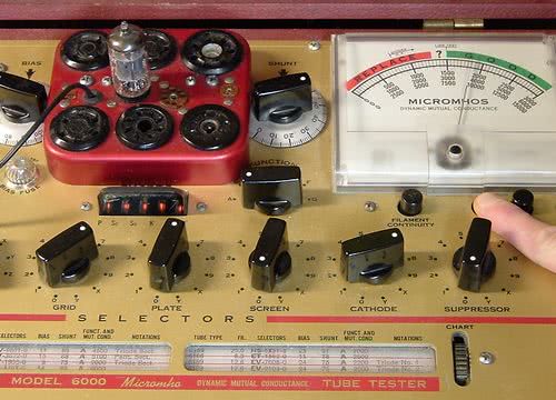
(as tested with calibrated B&K 707)
RESULTS:
- The Hickok tests this triode section at 1850 micromhos (2200 being NOS), which converts to a percentage score of 84%
- The B&K 707 tests this triode at 82%.
Hence, the scores are almost identical. The small deviation is most likely because of the different line compensation circuitry employed by Hickok and B&K.
regards,
Bob Putnak.
eBay ID = rjputnak
© 2008. All rights reserved. Article updates occasionally.