
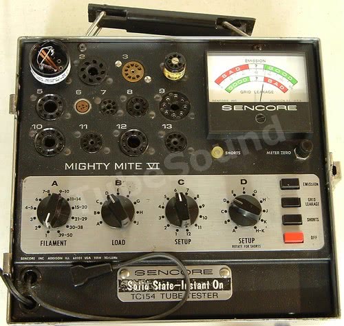
Sencore Mighty Mite solid-state tube testers (TC28 Hybrider, TC162, and TC154) are durable, easy-to-use, and test a wide variety of modern tubes (including modern sweep tubes such as #8950).


They were VERY popular among old-timer technicians. For most people, they are a very good choice.
Regardless of model, all the Mighty Mite solid-state models use the same basic circuitry, albeit configured slightly different among each model. Model TC162 is functionally equivalent to B&K 607 / 667.
Sencore outlines the Mighty Mite features as:

Circuit Description and Notes:
Cathode Emission Test
The cathode emission test method places AC voltage between the control grid and the cathode of the tube being tested. (For rectifiers and diodes, the test method places AC voltage between the plate and cathode.) The tube rectifies the AC voltage into DC; a load resistance (comprising either one resistor, or a series of resistors) is placed in series with the cathode to develop a pulsating DC voltage. The Load switch selects a predetermined voltage-load combination (one of 9 different selections) that is appropriate for the tube, and the resulting cathode current is measured and output to the panel meter, where the user can easily read the test result as Bad, Questionable, or Good.
The voltage-load combinations (control grid to cathode) on these Mighty Mites are as follows:
- Load A: 40 VAC, 150 ohms
- Load B: 40 VAC, 300 ohms (150Ω + 150Ω)
- Load C: 28 VAC, 300 ohms (exact same load resistance as B)
- Load D: 22 VAC, 520 ohms (150Ω + 150Ω + 220Ω)
- Load E: 22 VAC, 740 ohms (150Ω + 150Ω + 220Ω + 220Ω)
- Load F: 22 VAC, 1420 ohms (150Ω + 150Ω + 220Ω + 220Ω + 680Ω)
- Load G: 22 VAC, 11420 ohms (150Ω + 150Ω + 220Ω + 220Ω + 680Ω + 10KΩ)
- Load H: 40 VAC, 19620 ohms (150Ω + 150Ω + 220Ω + 220Ω + 680Ω + 10KΩ + 8.2KΩ)
- Load J: 40 VAC, 41620 ohms (150Ω + 150Ω + 220Ω + 220Ω + 680Ω + 10KΩ + 8.2KΩ + 22KΩ)
Load Voltages: Load voltages are easily checked by configuring the machine to test a 6L6 (do not insert a tube). Using a test socket in socket 1, measure the AC voltage between pins 5 and 8 while in Emission test position. Be sure to check the voltage at each Load switch position from A through J.

Of course, actual AC voltages will differ based upon input line voltage to the transformer primary. Typically, they will be a little higher without any tube in the socket, and lower when a tube is being tested.
Load Resistances: Notice that the load resistances are in series, therefore each previous load affects all of the following loads (except for Load C, which has the same load as Load B). For example, Load F’s 1420 ohms of resistance consists of: 150 ohms from Load A + 150 ohms at switch position B + 220 ohms at switch position D + 220 ohms at switch position E + 680 ohms at switch position F. Hence, it is easy to see that if any counter-clockwise load resistor is faulty, all clockwise loads will be incorrect. Therefore, any tweaking or recalibration of these load resistances must be performed starting at Load A and working clockwise.
Load resistances can be “fast” checked very easily. With unit powered off, using the same test socket as explained above, set the Load switch to position J and measure the resistance between pins 5 and 8 while switched to Emission test position. This is not a precision test because you are testing through the test entire circuit (not just the load string), but the resistance will be reasonably close to the load posted at Position J (which, as explained, includes all subsequent loads, thereby testing the entire string in one fast step).
Grid Leakage Test
The super-sensitive grid leakage test is probably the best attribute of a Mighty Mite. As the electron emitting material of cathode is worn away from age, some of the cathode material that has evaporated gets deposited on the grid. This causes the grid to incorrectly emit electrons – “grid emission”. This causes the grid to draw current and be more positive than it should be, thereby negatively affecting the circuit.

The tube under test has positive DC voltage (approx 8 vdc) applied to all elements except the grid, and the grid is biased beyond cutoff. (This DC voltage is measured in reference to (-) of electrolytic capacitor). If grid leakage is present, current will flow from grid to plate of the tube through the 30 meg resistance (R15 & R16 of TC162 schematic; R127 & R128 of TC28 schematic). This voltage is amplified by the solid-state amp, causing a deflection of the panel meter. The user then reads the Grid Emission scale on the meter to see whether the leakage is within the green-acceptable range or the white reject range.
The 100 megohms reject sensitivity is super-sensitive. Most tube testers will not measure leakage anywhere near this sensitive. The Sencore manual does a good job of explaining this benefit. “A lower sensitivity of 2 to 5 megohms found in many tube testers may eventually reject the tube but not during the time that it is being tested because tube heat causes the leakage to increase with time.” In other words, unless the tube was very hot and operating in-circuit, and then immediately inserted into a tube tester, it is unlikely that other testers would find the leakage. Since most tubes are tested “cold” (meaning not removed hot from circuit), you can readily see the advantage of the Mighty Mite leakage test. Continuing from the manual: “On some tubes, leakage may not reach this low level and the checkers with lower sensitivity will not find the ‘tough dog’ tube.”
Shorts Test
The Shorts Test selects one tube element, and all other tube elements are tied together.

The test places approx 34 VAC between this one selected element and all other elements.

As you rotate the Selector switch from 1 to 12, all tube elements are compared to each other. If the selected element has a short to any of the other elements, the Neon lamp (models TC154 and TC162) will light. The Neon lamp will just barely glow at 300K and will glow brighter as the condition approaches solid-short. Model TC28 indicates shorts using the meter scale, which allows for more accuracy than the 300K pass/fail test of the standard Mighty Mites.
Model TC162 and TC28 use lockout switches to ensure that false-positives are not reported, and also 100% ensures that all shorts between elements are detected. Model TC154 was an earlier model than the TC162 or TC28 and does not have lockout switches. Hence, when using the TC154, when testing tubes that have tube elements with multiple pin connections (ex: 6KG6 control grid is connected to pins 1 & 8; screen grid is connected to both pins 3 and 6; suppressor grid connected to both 2 and 7), the chart will tell you that tube will “normally show short B,C,F,G” or whatever the case may be. This method has less accurate shorts detection, though. Using the 6KG6 example, a real short between the screen and suppressor would not be properly detected because those two pins would normally show short anyway — and the tube chart would tell you that is correct behavior. That is why the lockout switching system was developed and incorporated into the newer models TC162 and TC28, which have 100% accurate shorts detection. In reality, this limitation in the TC154 affects only a relatively small number of tubes (tubes that have multiple elements that each have multiple pin connections). The most common of these tubes are Ham-Radio style sweep compactron tubes, such as 6KD6 or 6LB6. If you find a beautiful TC154, I would not hesitate to buy it, as this limitation is rather minor. These shorts would not be detected on any tester without lockout switches, regardless of tester brand.
Shorts detection is fixed at 300K in models TC154 and TC162 and without adjustment. The 300K detection will be close is the circuit is working correctly. Model TC28 does have a procedure (explained below) to calibrate the Shorts Test to factory specs.
LIFE TEST
TC162 and TC28 models incorporate a nicely designed, very useful, Life Test. The circuit (engaged on the front panel by a thumb slide switch) switches a small resistance (1-ohm) in series with the filament voltage, which drops the filament voltage to the tube under test. The cathode emission load test voltage remains unchanged, as those transformer windings / ac load voltages are not affected by this Life Test circuit. The result is a true life test that only drops the filament voltage, while leaving the cathode emission load voltage unchanged. It works very well.
The effect is significant when testing rectifier tubes and power output tubes. For example, while testing a new 5U4GB and engaging the life test, the emission reading is largely unchanged. When testing a used 5U4GB and engaging the life test, the emission reading will drop. While there is no fixed rule as to how much drop is acceptable, the less the drop, the better. A good rule of thumb is that if the emission drops into the red area, the tube is suspect. If the emission drops into the questionable area, the tube probably has useful life left. If the emission remains in the green, the tube should have comparable lifespan as a new tube.
Servicing the solid-state Mighty Mites
Make sure that you have a service manual. It contains circuit description, schematic, voltages, parts lists, troubleshooting chart, and calibration procedure.

Do you need a service manual and/or tube chart for your Sencore tube tester?
We offer a package for each tester, completely remastered service manual and large tube setup chart.
Sencore TC28 remastered manual & setup chart– $13.99 free ship USA

Sencore TC154 remastered manual & setup chart– $13.99 free ship USA
Sencore TC162 remastered manual & setup chart– $13.99 free ship USA
After 30-40 years you should expect that components fail — carbon resistors change value, wires break off under the testing sockets, contacts and switches are dirty and corroded, etc. Therefore, these things must be thoroughly checked before anything else is done. Check and replace all non-spec resistors, paying close attention to the load resistors. Check (or replace) all capacitors. Treat all sockets and switches with Deoxit. Look carefully for wires that have broken off from the sockets or worn insulation (causing shorts to the chassis or adjacent wiring.) Check continuity between all socket pins and proper continuity of Lockout switches (models TC162 and TC28). Check secondary transformer voltages (filament voltages and Load voltages). Check circuit board voltages as marked on the schematic. (Voltages are taken in reference to the (-) side of electrolytic capacitor.) If meter has suspicion of being defective, remove and test (0 – 1 DC mA for TC154 and TC162; o-100µA for TC28).
Some models have an undocumented AC line resistor in series with the transformer primary. Approx 100 ohms resistance, high wattage, and may be two 50 ohm resistors in series. The purpose is to drop the AC voltage down to 115V, which corresponds to the schematic documenting the primary as 115V. This modification is not present on all models (even in the same model number). It may have been due to a different transformer supplier, the reason is unknown.
The TC162 shipped with a ground line cord. The later revisions have a 1.5 meg resistor shunted with a 220pf capacitor connected between (B-) and ground. This modification is not present on the TC162 schematic.
The tester has three parts to its circuit: Emission, Shorts, and Grid Leakage. Common problems: No panel meter reading — check for bad 2N5457 transistor, bad zener diodes, or open panel meter. Emission problems — check the load resistors for opens. Shorts problem — check for opens in each pin circuit (loose wires or shorted wires at the sockets), check for shorts to chassis around the sockets, check the 82K and 8.2M resistors in models with neon lamp, check the 0.1, 0.0062 and 0.0056 caps. For grid leakage problems — check the two 15Meg resistors.
Need a pair of new socket savers to protect your tube tester sockets?
Buy a pair of new manufacture socket savers: 1 each SS-8 (octal) and SS-9 (9-pin-miniature). $29.99 free ship USA.
Note: The case lid will not close on many Mighty Mites with socket savers installed, especially when installing the octal socket saver. Buy at your own discretion.
Calibration
Now you are ready to use the Sencore Calibration Module and follow the instructions in the manual. IMPORTANT NOTE — several editions of the Mighty Mite manuals have typos regarding calibration. One version of the TC162 manual says that you should find shorts on 6 and 7. This is typo, it should read 5 and 6. One version of the TC154 manual says to check the Emission at “40” — it should read “60”.

I am frequently asked to explain how to make the Sencore Calibration Module, even though I mentioned above that these instructions are in the full Sencore Service Manual. I am adding the Calibration Module instructions here since it is a popular request, even though this is NOT a substitute to owning the service manual.


You really should not expect to properly service and calibration any piece of equipment without a service manual and schematic. This Sencore calibration module is NOT a magic bullet and using it without performing the prep work above is quite useless. ALL of the real work is in the circuit testing and preparation. Using the calibration module is nothing more than the last step of the repair process. Remember that these testers are approx 40+ years old — you cannot assume that any component is still within tolerance.
After calibrating, check a variety of new tubes of known value. Sylvania recommended using a new 7Y4 as the perfect calibration tube, because (in their words) “New type 7Y4 tubes have been found to be so uniform that only a point or so difference can be found in the readings of either plate for several tubes.” (Source: Sylvania 620 Service Manual, page 8.) The meter should read in the middle of the Green-Good range. Do not expect “digital” accuracy. A tube tester is an analog device, and analog accuracy is all that is achievable.
TC28 Hybrider
TC28 Hybrider is calibrated a little differently. Model TC28 is easily one of the best tube testers that Sencore manufactured. First-class in every way – a truly fine test instrument with exceptionally high build quality. TC 28 dimensions (inches): 15 x 12 x 5. Weight is approx 14-lbs.
The TC28 uses its large panel meter to indicate all testing functions: Emission, Grid Leakage, and Shorts.
For your convenience, I have prepared the TC28 calibration steps as PDF download: [TC28_Calibration_Steps_PDF]
In condensed summary, TC28 calibration steps are:
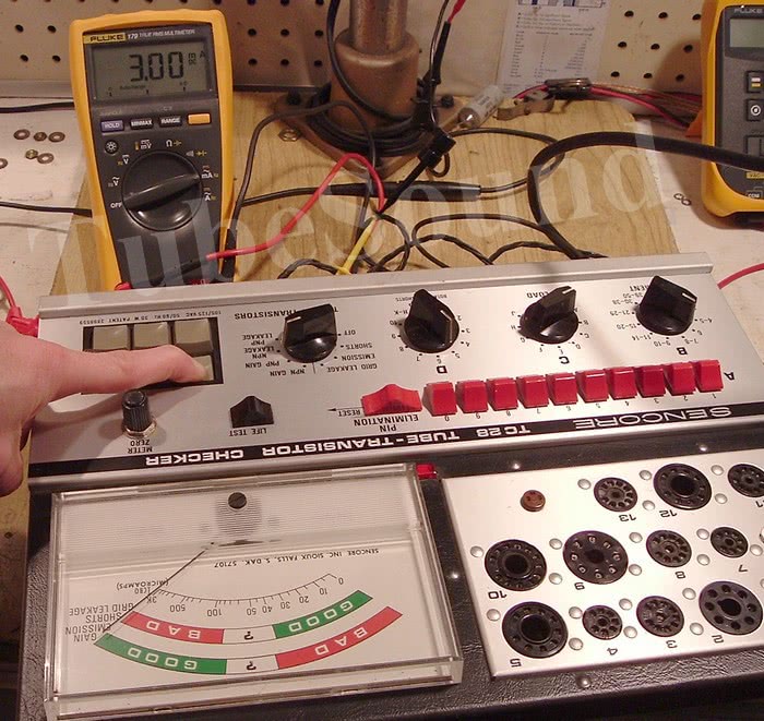
After adjusting the mechanical-zero adjust on the meter of the TC28 for a “0” indication, apply AC power to the unit and turn the Function Switch to the NPN LEAKAGE position. Connect the positive terminal of a DC milliammeter to the red test lead. Connect a 2000 ohm variable resistor (or versatile resistor substitution box) between the negative terminal of the milliammeter and the yellow test lead. Press TEST button No. 1 and adjust the external resistance until the milliammeter indicates 3.0mA. While still pressing TEST button No. 1, adjust R101 (the Leakage Cal. Control) for a full scale indication on the TC28 meter.
Insert calibration module and setup A-D controls as directed. Set the Function Switch to SHORTS and adjust the meter to zero with the front panel METER ZERO control. Switch to the GRID-LEAKAGE position on the Function switch and adjust R132, the Grid Leakage Cal. Control, until the meter reads on the line that demarcates the separation of the “?” and BAD on the GRID LEAKAGE scale on the meter. Switch back to SHORTS and recheck the meter zero. Readjust METER ZERO control if necessary. Repeat step to achieve continuity.

Change the setting of the SETUP “D” switch from position 4 to position 3. Set Function Switch to EMISSION and adjust R103, the Emission Cal. Control, until the meter indicates “?” (center scale) on the EMISSION/GAIN scale of the meter. Switch back to SHORTS and recheck the meter zero. Readjust METER ZERO control if necessary. Repeat step to achieve continuity.

Change the setting of the SETUP “D” switch from position 3 to position 5. With the Function Switch in the SHORTS position, adjust R105, the Short Cal. Control, so that the meter indicates on the line between GOOD and “?” on the GRID LEAKAGE – SHORTS scale of the meter.

This is also part of the Shorts test. Change the setting of the SETUP “D” switch from position 5 to position 7 and observe that the meter indicates zero. Adjust the front panel METER ZERO if required. Recheck previous step, and then this step, for continuity. This completes TC28 factory calibration steps.

A final note, you should NOT expect that a Mighty Mite will give “test scores” identical to a Hickok, B&K, or any mutual conductance tester. That is a different testing method. You will even find variation among Emission testers, because the Good-Bad scale for Emission testers is not implemented consistently among every manufacturer. These are facts, and probably the most difficult concepts for novice users to grasp. I say “novice” — not based upon quantity of tubes they buy or sell, but based upon their knowledge of the electronics involved.
Tube Chart “extras” —
The following section will be updated when chart mistakes are found, or if I had a reason to create settings for a tube that was not on the chart.
TC162 and TC28
- 420A. (Triode 1) A=9, B=12, C=F, D=3, Socket=3. (Triode #2) A=9, B=12, C=F, D=6.
- 5755. (Triode 1) A=9, B=12, C=F, D=3, Socket=3. (Triode #2) A=9, B=12, C=F, D=6.
- 7119. (Triode 1) A=8, B=12, C=D, D=2, Socket=3. (Triode #2) A=8, B=12, C=D, D=7.
- 8950. A=1,6,7,9,0, B=13, C=A, D=5, Socket=10
- M2057. A=1,6,7,9,0, B=13, C=A, D=5, Socket=10
regards,
Bob Putnak
eBay ID = rjputnak