
©2011, Bob Putnak. This post examines the performance (directly related to the input impedance) of low-cost meters; specifically, I explore a common multipurpose Colluck PM-128E DPM (digital panel meter) and a bargain-priced Cen-Tech #98025 multimeter.
Limitations in the design of these low-cost meters can severely affect measurement accuracy. First of all, I prove that the input impedance of the PM-128E is 1-megohm, not the 100-megohms or 10-megohms that is specified by the manufacturer and most vendors that sell this DPM. Second, I demonstrate that the input impedance of the Cen-Tech #98025 multimeter is also 1-megohm. The conclusion is that either meter will not accurately measure high-impedance circuits, and both perform poorly at measuring low AC voltages. They can be suitable for other types of measurements, though.
First a little background –“Input Impedance” as it pertains to a meter — is the load that the meter places upon the circuit being measured. Ideally, a perfect meter would have no loading effect, but all meters have some loading effect on the circuit they are measuring.
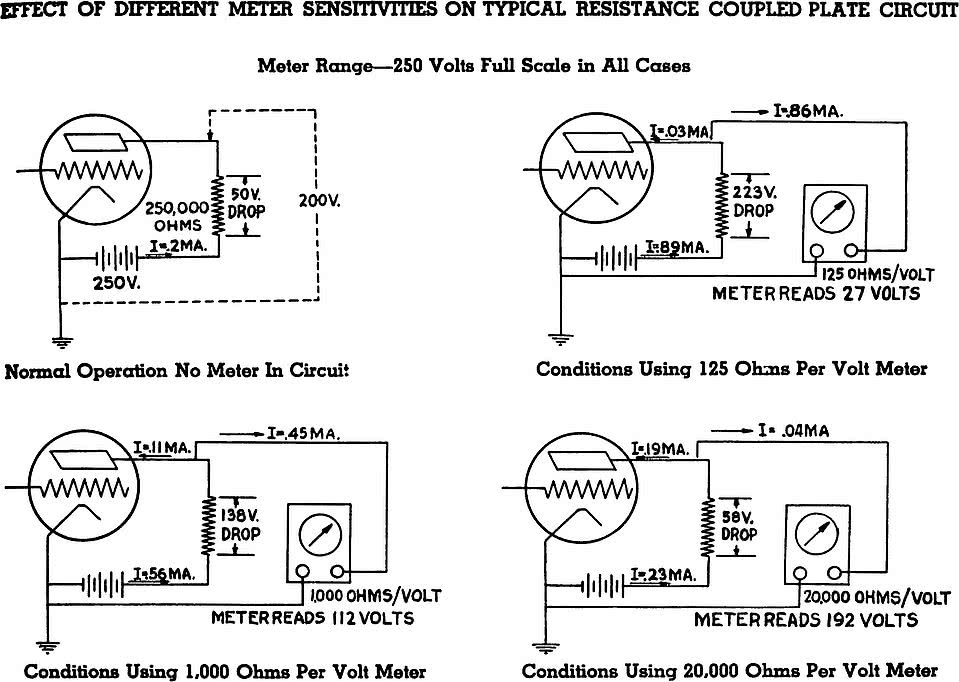
For example, early analog VOM’s had an input impedance of 1000 ohms per volt, which meant that when the meter was set on the 500v range, the input impedance was 500k ohms. This input impedance (sometimes called ‘meter sensitivity’) is the exact same as placing a 500k resistor across the circuit. Newer analog VOM’s had an input impedance of 20,000 ohms per volt; therefore using our 500v range as the example, the 20,000 ohms/v meter would only load the circuit at 10-megohms. VTVM’s (vacuum-tube voltmeters) and TVM’s (transistorized voltmeters) commonly had a fixed loading effect of 11-megohms or 22-megohms, regardless of measurement range. Most quality modern DMM (digital multimeters) have a fixed input impedance between 10-megohms to 11-megohm. The higher the input impedance resistance, the more accurate the measurement. Input impedance is a serious issue when measuring high impedance circuits.
PM-128E DPM
Depending on where you look on the Colluck website, the manufacturer lists the input impedance as either 10-megohms, and in other places on their website, they publish a specification of 100-megohms. In reality, I measure that the meter has a fixed input impedance of 1-megohm on every DC measurement range, and since most users will use the PM-128E to measure DC voltages, knowing the DC input impedance is paramount to understanding how accurately it will perform.
Proving this fact is rather easy, and here are 2 way to prove input impedance.
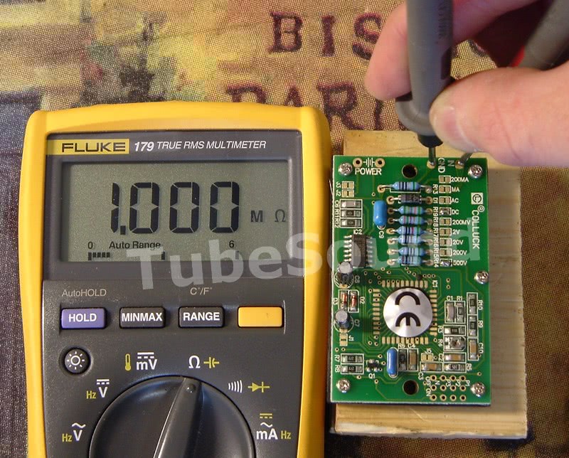
1. You can easily measure the resistance across the input terminals using your DMM. Here, you see the input impedance is exactly 1 megohm as measured with my Fluke meter.
2. In the second example, I mocked up a simple test circuit using a 400V regulated power supply voltage and two matching 1-megohm 1% resistors in series, for a total series resistance of 2 megohms. Ohm’s law tells you that each 1-meg resistor will drop 200V, and has a series current of 200 µA. This is exactly how the circuit is performing in real life, without any attempt to measure it. This is an example of a high-impedance circuit.
So how did the PM-128E perform?

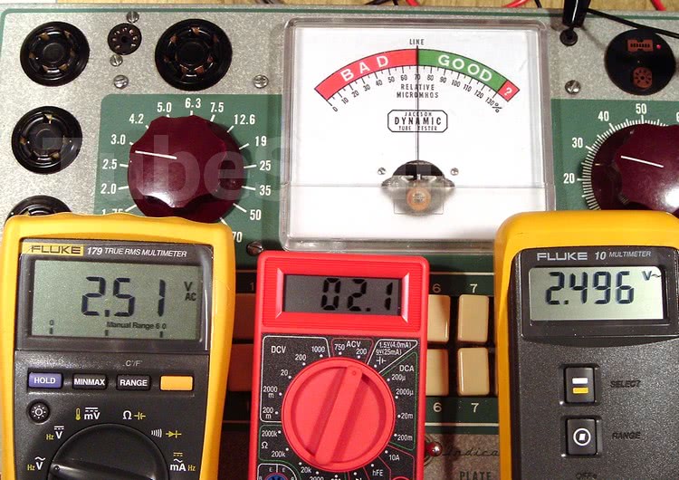
With the PM-128E connected across one of the precision 1-megohm resistors, the new circuit resistance is only 1.5 megohms (1 megohm precision resistor, which is in series with parallel combination of 1-meg resistor shunted by 1-meg internal impedance of PM-128E meter).
Ohm’s law reveals that the new series current is 266.667 µA, and ohm’s law reveals that the voltage across 0.5 megohms with 266.667 µA current would yield a voltage of 133.3 volts, which is exactly the measurement that the PM-128E provided.
Hence, what should be a 200v measurement is only reading 133v on the PM-128E, a very large error.
Cen-Tech #98025 multimeter
As you see from these next photos, the Cen-Tech #98025 multimeter performed identical to the PM-128E panel meter. The circuit analysis is therefore identical. (The Cen-Tech #98025 multimeter instruction manual does not specify its input impedance.)


The third photo here demonstrates inaccurate measurements of low AC voltages. The PM-128E (which has an AC measurement function) also performs poorly at measuring low AC voltages. Coincidentally, the PM-128E will give the same reading as the Cen-tech #98025, leading to a suspicion that they share a common circuit design. I do not know the cause of the poor AC measurement performance.
Contrast the performance of the meters above with the measurement from my Fluke #10 DMM. I chose the Fluke #10 since it was an entry-level Fluke. (The PM-128E and Cen-Tech have been, of course, removed from the circuit).
Here is the circuit analysis with the Fluke meter across one of the 1-megohm resistors: my Fluke #10 has an input impedance of approximately 10-megohms. Therefore, with the Fluke #10 shunted across the 1-megohm resistor, the parallel resistance has changed from 1-megohms to 909k ohms, and therefore 909k ohms in series with the other 1-megohm resistor yields a new series resistance of 1.909 megohms, with a new series current of 209.534 µA.
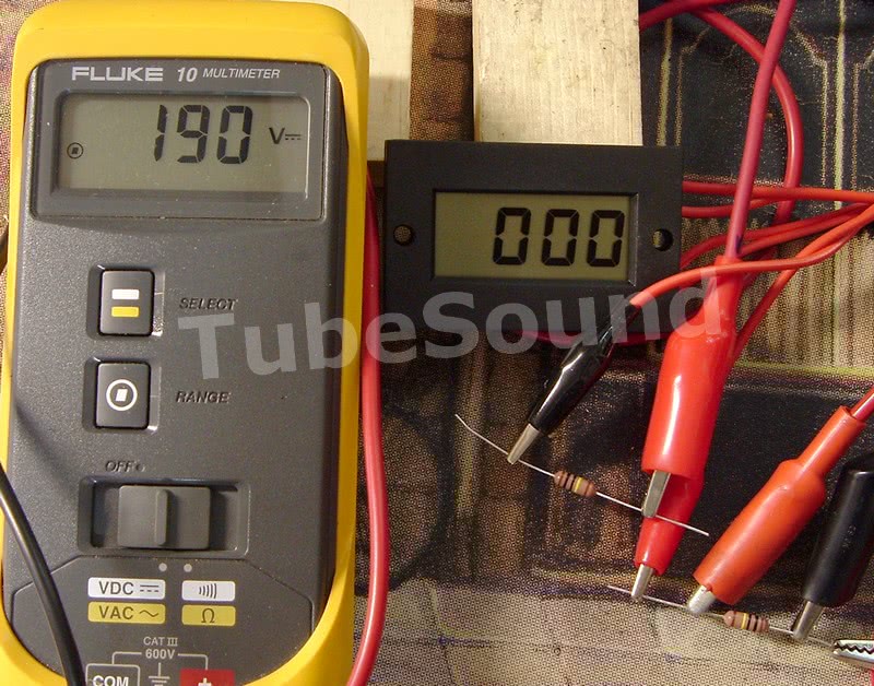
Ohm’s law reveals that the voltage across 909k ohms with 209.534 µA current should measure 190.46 volts. As expected, the Fluke #10 measurement is 190V, which is 57 volts higher than the reading given by the cheap meters.
This 190V reading is much closer to the 200V drop that is, in fact, how the test circuit performs when not being probed by any meter.
CONCLUSIONS:
1. you need to understand your meter to use it effectively.
2. when you understand your meter, you will realize what type of measurements it cannot perform with any degree of acceptable accuracy.
3. the input impedance of the PM-128E is, in fact, 1-megohm for all DC measurement ranges.
4. the input impedance of the Cen-Tech #98025 multimeter is, in fact, 1-megohm for all DC measurement ranges.
5. Neither meter is suitable to measure high-impedance circuits because of circuit loading from its 1-megohm input impedance. Therefore, high impedance circuit measurements will be wildly inaccurate. For low-impedance circuits, either meter is suitable and a good value for its low price.
6. Do not rely on published specification from vendors or even the manufacturer. In this example, the published specifications for input impedance of the PM-128E are usually wrong. I was told by one vendor that because the IC inside the meter has a 10-megohm impedance, that factoid somehow makes the published 10-megohm specification “reasonable”. I disagree. You are not buying an IC, you are buying a meter, and the meter cannot be configured so that its input impedance is better than 1-megohm. Therefore, as far as I am concerned, it has a 1-megohm input impedance in reality. As of 09-2011, MPJA pdf datasheet accurately reflects product specification of 1-megohm input impedance for the PM-128E, although their website product page description now parrots the same info from the manufacturer.